Continue to Site

Welcome to our site!

Electro Tech is an online community (with over 170,000 members) who enjoy talking about and building electronic circuits, projects and gadgets. To participate you need to register. Registration is free. Click here to register now.

  • Welcome to our site! Electro Tech is an online community (with over 170,000 members) who enjoy talking about and building electronic circuits, projects and gadgets. To participate you need to register. Registration is free. Click here to register now.

Newbie question: Pulse On-off switch

Status
Not open for further replies.

Migs

New Member
Friends:

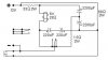
Where do you all look on the internet to find a circuit diagram? I need a simple diagram for a push switch that when I push it once it closes a switch and keeps it closed until I pulse it again (think of spring loaded switch that always disconnects when the presure is released). One pulse turns on an LED circuit and another turns it off.

The switch must run off 3, 6 or 9vdc.

Thanks amigos!

Migs
 
Switch.

Hi Migs,

Is this the kind of circuit you were looking for ?

on1aag.
 

Attachments

  • Switch.GIF
    Switch.GIF
    6.7 KB · Views: 2,888
More. Several different circuits.
 

Attachments

  • Flip Flop Solid State Relay.gif
    Flip Flop Solid State Relay.gif
    3.6 KB · Views: 2,464
  • One Button Relay.gif
    One Button Relay.gif
    5.7 KB · Views: 2,546
  • Pulse Relay FF.jpg
    Pulse Relay FF.jpg
    12.5 KB · Views: 1,717
  • Single switch Latch relay.gif
    Single switch Latch relay.gif
    29.3 KB · Views: 3,080
Hi on1aag and hotwaterwizard:

Thanks for these schematics, I will analyze them and get back to you if I dont understand.
on1aag: What are the "S" Items in the schematic?

Thanks amigos!!! -Migs
 
"S" items.

Hi Migs,

The CD40106 is a hex inverter, the "S" is not an "S". It's the symbol
that means that these inverters have Schmitt-trigger inputs.

With kind regards,

on1aag.
 
Hi on1aag:

I would have to use 6 CD40106's for the switch? The symbol on the right is a LED?

Thanks amigo!

Migs
 
The CD40106 is a HEX inverter. HEX means six. It has the six inverters inside. Lookup its pin numbers on its datasheet.

Yes, the LED symbol is an LED, the resistor symbols are resistors and the capacitor symbol you will have to guess what it is.
I recommend using a battery or power supply for the circuit.
 
Why bother, when you can buy switches that will already do this?
 
Hero999 said:
Why bother, when you can buy switches that will already do this?
Because their toggling mechanism quickly wears out. Push it's on, push again and it's off, push again and it's stuck!:D
 
Tarsil:

Do you know of a circuit like the one you showed that latches the switch closed until the next press?

Migs
 
Migs said:
Tarsil:

Do you know of a circuit like the one you showed that latches the switch closed until the next press?

Migs
How about conecting a bistable built with a 555. U should find info about this on this site. Use inverters (NOT gates) if needed from a 4069 or so. Was my confusion ...I didn't read carefuly the post:D . U can also google for "touch switch". U'l found a lot of links.
 
audioguru said:
Because their toggling mechanism quickly wears out. Push it's on, push again and it's off, push again and it's stuck!:D
If you buy a cheap and nasty switch then yes. The vacuum cleaner has a 10A motor and it's push button switch still works and it's years old!
 
Migs said:
Do you know of a circuit like the one you showed that latches the switch closed until the next press?

The CD40106 circuit changes and latches until the pushbutton is pressed again. It is called Alternate Action. Here is a circuit with just the first part shown that is nearly the same but it uses an ordinary CD4069 Hex Inverter IC without Schmitt Trigger inputs. The remaining 4 unused inverters can be paralleled and used as a current-booster like in the CD40106 circuit.
 

Attachments

  • Alternate-action.gif
    Alternate-action.gif
    3.6 KB · Views: 1,582
Status
Not open for further replies.

Latest threads

New Articles From Microcontroller Tips

Back
Top