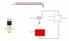
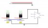
If you want to try it with two 7805's then you have to set the second one up such that its ground terminal connects to the OUTPUT of the first 7805, and that same output becomes the new ground for the op amp. That gives you plus and minus 5v where ground of the 18v supply looks like -5v to the op amp, and the output of the second 7805 looks like +5v to the op amp, and the common connection of the two looks like ground to the op amp.

")