PG1995
Active Member
Thanks, MrAl.
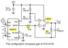
I don't get it. In my humble view the picture shows A1 connected in inverting configuration and A2 connected as a buffer with unity gain. Where do I have it wrong?
Please have a look here. Suppose Vin=10V and voltage drop across R_sense is 1V. The gain of A1 is set at -(1/4). In the given case, differential voltage, V_diff, is: V_diff = 9-10 = -1. The order of subtraction is important here. We cannot write (10 - 9) because we are applying the input voltage to inverting input of A1 and not non-inverting input.
The Vout would be (V_diff)(gain) because it's the differential voltage which gets amplified. Therefore, (-1)(-1/4) = 1/4. Do I have it correct? Could someone please let me know? Thanks.
Regards
PG
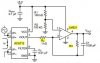
Just a quick note for the picture "sensor222.jpg".
A1 should be connected as a differential amplifier. It's not really right the way it is now.
A2 should be connected as a buffer or not used at all. It's not connected right the way it is now.
I don't get it. In my humble view the picture shows A1 connected in inverting configuration and A2 connected as a buffer with unity gain. Where do I have it wrong?
Please have a look here. Suppose Vin=10V and voltage drop across R_sense is 1V. The gain of A1 is set at -(1/4). In the given case, differential voltage, V_diff, is: V_diff = 9-10 = -1. The order of subtraction is important here. We cannot write (10 - 9) because we are applying the input voltage to inverting input of A1 and not non-inverting input.
The Vout would be (V_diff)(gain) because it's the differential voltage which gets amplified. Therefore, (-1)(-1/4) = 1/4. Do I have it correct? Could someone please let me know? Thanks.
Regards
PG
Attachments
Last edited: