PG1995
Active Member
What exactly are you talking about here? If you see a problem you must state what it is.
I didn't mean much. I was trying to say that to keep track of the details such as 10-bit ADC is being is used, the voltage output of current sensor IC, etc.
Yes, in general some gain can help because the circuit then takes better advantage of the ADC input range. Of course it also amplifies any error present in the sensor. If the gain is too high, it could also push the op amp output out of range.
4.7k might be ok, but you do have to check the op amp output at the plus and minus input extremes to make sure that it can actually get to those values.
So, gain can help. I need to design this circuit so that's why I wanted to confirm it.
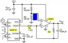
I believe 4.7k would do better than 5.1k because this way the output won't go near the rail voltage. Note that we are dealing maximum current of 2.3A and in this circuit the value R3 was chosen to be 5k.
Moreover, don't you think that using a capacitor like this next to non-inverting input of the op-amp a good idea? A small value capacitor such as 22-33 pF would be okay.
If possible, please also have a look on this part from previous post which you didn't address in your last post.
This is a general query. If a single supply op-amp is power by +5V supply then the its lower rail voltage is ground. I mean to say that its output voltage cannot go negative.
NorthGuy: I hope you are following this discussing about the current sensor. I'm not able to find any other current sensor other than the given one. Using a shunt might be a better idea but in my view for someone like me who don't have any experience with designing real circuits this might pose a problem by making the circuit more messy and error prone. If you or anyone else have any better current sensor IC in mind then please let me know because it's possible that I might need to order some stuff from online dealer such as Digikey. Thanks.
Regards
PG
") I used
I used