Thank you, KISS.
So, I had it correct though I'm also waiting for MrAl's comments. I'm still confused about two points.
Perhaps, to be precise, you should have written |input offset| = |output offset|. Please let me know if I have it correct. I understand that there isn't really a big difference but to me it might indicate a loophole in my understanding.
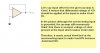
In
this picture from my previous post, Vout was confirmed to be -2mV. The input offset voltage is said to be differential voltage. The differential voltage is Vdiff = Vin - Vf where Vf is feedback voltage. In that buffer circuit input offset voltage was taken to be 2 mV, i.e. Vdiff=+2mV. The Vf was -2mV. It gives Vdiff=Vin-Vf => Vin=+2mV+2mV=4mV. The Vin for that circuit should have been +4mV and not +2mV. Where am I going wrong? I believe that input offset voltage isn't really the differential voltage I'm familiar with.
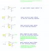
Please also help me with this
next step. Thank you.
Regards
PG

")