PG1995
Active Member
Hi
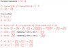
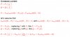
It was written that P=Po(V/Vo)^alpha and Q=Qo(V/Vo)^beta. Later, it was said that if alpha=beta=2 then you get a constant impedance, and also if alpha=beta=1 then you get a constant load. I believe that 'Q' stands for reactive power and 'P' for real power.
I couldn't make any sense that how the two formulas above were reached at and how and why alpha=beta=2 results into a constant impedance and so on. Could you please help? Thank you.
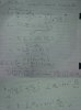