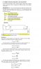
I don't think so because in this section on balanced Y-Δ configuration, it clearly says that phase voltage and line voltage are different. In this text, which, by the way, I use the most, phase voltage is defined as line to neutral.
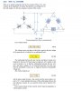
But I think that mentioned text is confusing because I checked three other texts on that and phase and line voltages for Y-Δ configuration are taken the same. In
one text, phase voltage, Van, for the alternator and phase voltage, Vab for the load are taken differently. In
the other, phase and line voltage are considered equal. The text which the problem under discussion is taken from also considers phase and line voltages equal.
Thanks.