Continue to Site

Welcome to our site!

Electro Tech is an online community (with over 170,000 members) who enjoy talking about and building electronic circuits, projects and gadgets. To participate you need to register. Registration is free. Click here to register now.

  • Welcome to our site! Electro Tech is an online community (with over 170,000 members) who enjoy talking about and building electronic circuits, projects and gadgets. To participate you need to register. Registration is free. Click here to register now.

odd signals from transimpendance amplifier

Status
Not open for further replies.

BraveWart

Member
I am building a setup to be able to read the reflected light from a laser beam with a photodiode, which I have never done before.
so I bought this photodiode and this transimpendance amplifier. But after wiring it up, I didnt get any useful readings from the TIA.
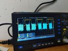
So I I reduced the voltage from my signal generator with a voltage divider and checked in on the oscilloscope.

But I I cannot interpret what I am seeing there:

PXL_20230212_133435665.jpg

sine

PXL_20230212_133441292.jpg

square

PXL_20230212_133444730.jpg

triangle

This is my setup
PXL_20230212_133618239.jpg


Is this a case of a broken module?
Is the voltage divider wrong? P-P amplitude from the signal generator is about 5.6V. I reduced this to around 500mV with the Voltage divider

I expected it to mirror the input signal at a simnifically increased voltage level.
Is using a waveform generator for testing the wrong approach?
I am a hobbyist and this is all a bit trial and error for me.

I know the photodiode works as it reacts to light when connecting directly to the oscilloscope.
 

Attachments

  • PXL_20230212_133441292.jpg
    PXL_20230212_133441292.jpg
    1.2 MB · Views: 162
A transconductance amp amplifies current, so you need to put a large resistor in series with the input for the signal from you generator (since I see no specs for the amp, I can't tell you the best resistor value you should use but start with 100kΩ).

Without a resistor you are likely looking at the open loop gain of the amp, so all you see at the output is some version of a square-wave or oscillation/noise, no matter how small you set the input from you generator.
 
Last edited:
Thank you for all the helpful replies.
So, good to learn that testing the module with a signal generator is not wrong. I Have added a resistor through a voltage divider in front of the TIA. But probable not enough. I will try tonight getting the signal down to 100mV with different resistors.

Unfortunately I couldn't find a datasheet for my TIA, so I have no idea what the input range is. All I could find was a circuit diagram.
I have an idea now why the diode might not have given me any signal now. Because I didn't connect the reverse Voltage to the TIA module. What I did was following this clue from the sellers page:
H3b378ec8ec564f6ab566a1dc7cf3f2e5C.jpg

In the first picture the reverse voltage is also not connected (left top connector). But of course they wouldn't connect it for the shown test, because they also just used a signal generator and not a photodiode that requires it.
I will do all this tonight and give an update.

Thank you all.
 
Unfortunately I couldn't find a datasheet for my TIA
It say both in the listing and in the schematic you posted that it uses an AD8015, which I posted the datasheet for in my previous answer?


However, that module schematic is crazy!

It shows a capacitor (C4) in line with the input pin (pin 2), so you cannot feed the DC bias from a photodiode through it.

And, C3 pretty much shorts out the input at high frequencies!

I'd remove R2 and C3, and link out C4 so the module input connects directly to pin 2 of the IC. It should then hopefully work as the IC datasheet shows.
 
A transconductance amp amplifies current, so you need to put a large resistor in series with the input for the signal from you generator (since I see no specs for the amp, I can't tell you the best resistor value you should use but start with 100kΩ).

Without a resistor you are likely looking at the open loop gain of the amp, so all you see at the output is some version of a square-wave or oscillation/noise, no matter how small you set the input from you generator.
I added the 100k resistor between the voltage divider and the TIA and got the same results. Then I changed the voltage divider so I get 100mV output like seen in the example screenshots by the seller above.

Now I just get a sort of cleaner Square form back from the TIA
PXL_20230213_175152793.jpg

PXL_20230213_175225956.jpg
PXL_20230213_175224506.jpg


I have also added 5V reverse Voltage to the corresponding pin on the tia, which raises the level, but doesn't change the signal.

Then I reattached the photodiode like in the schematics mentioned by danadak and rjenkinsgb. But as before, all I get here is a neat, clean straight line that doesn't react to anything (I cover and uncover the diode from light).

The reason I bought this particular module was because it advertised to be super fast and I assume to be having to measure high frequencies with the diode later down the project.

As this is my first touchpoint with photodiodes, I got to ask: is this even the right approach? How does one read the signal from a photodiode "normally"?
 
The reason I bought this particular module was because it advertised to be super fast and I assume to be having to measure high frequencies with the diode later down the project.

The IC is ultra fast; the PCB module adds components that restrict both low and high frequencies, as mentioned in my previous post. They need removing / bypassing.
 
The IC is ultra fast; the PCB module adds components that restrict both low and high frequencies, as mentioned in my previous post. They need removing / bypassing.
ok will do next. Also will have to further reduce the input signal from the waveform generator as it still saturates the IC. I just didnt have the required resistors at hand today.
 
Status
Not open for further replies.

New Articles From Microcontroller Tips

Back
Top