psecody
Member
So I've got a circuit that I'm working on where I've got a tach generator outputting AC signal (0-~70V) that I'm trying to measure the frequency of using a ATTiny328P. I've gotten the ATTiny programmed and working on the bench testing with a function generator set to square wave with a DC offset so that the signal is between 0V and ~5V, all that's working as it should. The sensor unit is where I've run into some issues that I can't really explain and was wondering if anyone had any thoughts on it, it's probably something little and stupid that I have overlooked but I just can't seem to figure out why it's behaving the way it is.
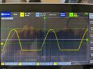
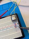
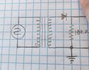
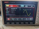
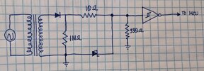
Disregarding the rest of the system for a minute, I have an 80Hz sine wave (20V peak to peak) coming in to a 2:1 transformer(TY-250P) then going through a 1N4007 diode and a 10kΩ resistor. My issue is that on the oscilloscope I'm still reading negative voltage instead of the diode cutting the waveform off at 0V like I was expecting. I've tried a ton of different configurations and am still having negative voltage (which the MCU doesn't like, which is why I'm trying to figure this out.) Anyone have any thoughts as to why this might be happening? I've attached photos of the schematic, of the circuit on a breadboard, and of the oscilloscope. Using the falstad circuit simulator it works as I would expect but in real life I'm seeing a negative voltage on the circuit. (EDIT: In the pictures the voltage will be different because I have the transformer reversed right now for 40V peak to peak since my function generator maxed out at 20V peak to peak. Also the ground reference for the probe is connected to the ground bus running up the middle of the breadboard and is not in the picture but it's the blue row on the breadboard.)
Any help would be appreciated because I am just befuddled with this. It's been a while since I've worked with electronics in any serious sense so I'm trying to refresh my memory on things and may have just missed something. Thanks in advance for any thoughts on this, they are much appreciated.
