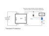
Place the fuse in series with the high side of the load.
You can likely use an automotive fuse rated for 32 VDC. I believe this began with a 36 VDC application and I don't believe the additional few volts will matter. Auto supply store should have what you need. That or take a look at McMaster Carr Supply if you have one locally.
Ron
You can likely use an automotive fuse rated for 32 VDC. I believe this began with a 36 VDC application and I don't believe the additional few volts will matter. Auto supply store should have what you need. That or take a look at McMaster Carr Supply if you have one locally.
Ron
")

