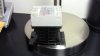
Continue to Site

Welcome to our site!

Electro Tech is an online community (with over 170,000 members) who enjoy talking about and building electronic circuits, projects and gadgets. To participate you need to register. Registration is free. Click here to register now.

  • Welcome to our site! Electro Tech is an online community (with over 170,000 members) who enjoy talking about and building electronic circuits, projects and gadgets. To participate you need to register. Registration is free. Click here to register now.

Need Advice On The Best Type of Switch For This Application...

Status
Not open for further replies.
Yes, you do need a heatsink if the load is on for any significant time. If you don't have a substantial metal chassis to mount it to then the heatsink you referenced should work fine. Heatsink compound is also recommended and it is the same as used with a computer CPU heatsink.
 
Yes, you do need a heatsink if the load is on for any significant time. If you don't have a substantial metal chassis to mount it to then the heatsink you referenced should work fine. Heatsink compound is also recommended and it is the same as used with a computer CPU heatsink.

Cool! and ordered! :)

Can't wait to get this in the mail and try it out. I'm hoping the input current limit for the cheap 25A SSR is similar to the expensive relay. I'll look around and see if I can find a datasheet for it.
 
Hey Carl,

Using the SSR, will I need a diode as shown in the wiring diagram attached?
This photo came from the expensive SSR datasheet.

If so, will the one you refereed to earlier be okay?
 

Attachments

  • screenshot.2.jpg
    screenshot.2.jpg
    28.1 KB · Views: 144
Last edited:
Here's the company website that has a data sheet for the relay.

Yes, you need a diode across any load that's inductive to prevent voltage spikes from zapping the relay. The 1N4002 should work fine.
 
Here's the company website that has a data sheet for the relay.

Yes, you need a diode across any load that's inductive to prevent voltage spikes from zapping the relay. The 1N4002 should work fine.

Alright, ordered!

I went to their site but the only information they provide on the SSR DC-DC is on this page which doesn't even list my device lol: FOTEK

I went with their 40A model instead of the 25A model since it was only $2.00 more :), but I'm amazed at how much little info they provide for their products and the 1990s website design they have :p

But maybe the 7.5mA trigger current they have listed for the 5A model will apply for my 40A SSR?

I'll do some more digging though in the meantime.
 
Well I just found a datasheet for the DC input / AC output FOTEK 40A SSR here: https://www.electro-tech-online.com/custompdfs/2011/05/29-FOTEK-SSR-xx.pdf

It as well is stating a 7.5mA trigger current or below, so is it safe to assume that the DC input / DC output FOTEK 40A SSR will have the same requirements?

Also, if so, I'm curious to why it has it as: 7.5mA / 12v

What is the 12v part for?
 
Well I just found a datasheet for the DC input / AC output FOTEK 40A SSR here: https://www.electro-tech-online.com/custompdfs/2011/05/29-FOTEK-SSR-xx-1.pdf

It as well is stating a 7.5mA trigger current or below, so is it safe to assume that the DC input / DC output FOTEK 40A SSR will have the same requirements?

Also, if so, I'm curious to why it has it as: 7.5mA / 12v

What is the 12v part for?
Chances are they all have the same sensitivity since that is determined by the opto-coupler characteristics and not the output voltage or current.

The input is an LED and has a resistor (or some more elaborate circuit) to limit the input current. It is designed so the input will operate properly over a relatively wide voltage range. The 7.5mA / 12V just means that at 12V input voltage the input current will be 7.5mA. This current will vary with the input voltage.

Oh okay, so really when I get this thing in the mail, all I should have to do is hookup an output from my microprocessor to the input, and wire the motor connection plus the diode to the output portion of the SSR, and be done with it?

Since my uP only outputs 5v, and as you stated, the SSR will operate properly over a relatively wide voltage range, no external resistor on the input side should be needed? I think I've answered my own question, but just trying to confirm everything so I know exactly what to do when I get it, and if I've ordered everything I need :)

Thanks for your help also!!!
 
Sounds like you are good to go.:D
 
FOTEK is in Taiwan and their Engrish is horrible. They say the input voltage range is 3W to 30V so take a guess what it means.
 
FOTEK is in Taiwan and their Engrish is horrible. They say the input voltage range is 3W to 30V so take a guess what it means.

Obviously they ran out of the letter V so they used a W but forgot to chop part of the W off to make it a V. Very common practice in Taiwan. Because of their geographical location they constantly have problems stocking the letter V.

Actually I was surprised at the low cost of their SSRs. I hope they work well. :)

Ron
 
Since my uP only outputs 5v, and as you stated, the SSR will operate properly over a relatively wide voltage range, no external resistor on the input side should be needed? I think I've answered my own question, but just trying to confirm everything so I know exactly what to do when I get it, and if I've ordered everything I need :)

Thanks for your help also!!!

I would energize that SSR from a 5v power supply and measure its current draw before letting the uC assume control and possibly zapping its output pin. If it needs more than the uC can provide you'll still have work to do. 7.5ma @ 12v might be anything @ 5v. Nobody knows.
 
Last edited:
The SSR has a resistor in series with the internal LED. The resistor would be ~ (12V-1.7V)/7.5mA = 1.3K. So, at 5V the current will be ~(5-1.7V)/1.3K=2.5mA.

Ken
 
Last edited:
I would energize that SSR from a 5v power supply and measure its current draw before letting the uC assume control and possibly zapping its output pin.

Wait, first, what does uC mean lol (unit controller?)?

If it's just another name for the microprocessor, then how exactly will the microprocessor zap itself (or as you stated, it's output pin).

As far as being able to provide enough current, I know the 5v output can supply 7.5mA as the average LED draws about 20mA, and I can power an LED easily with an output pin from the microprocessor.
But yes, I will hook up a power supply to it and monitor how much current it's pulling at 5v.
 
Wait, first, what does uC mean lol (unit controller?)?
It actually should be µC for microcontroller but sometimes the Greek letter mu (which is the micro prefix such as µF) is not available in the available font (although it is here) so u is commonly used in place of µ.
 
Well I just received my SSR in the mail as well as the heatsink for it, however, the company forgot my heatsink compound!!!

I was curious if regular arctic silver 5 thermal compound (Arctic Silver 5 Thermal Compound : Computer Cooling Systems | RadioShack.com) would due, as I don't want to cause too much fuss over something that cost $0.50 and also have to wait 3-4 more days to get it shipped?

Attached is a photo of the SSR attached to the heatsink...it fits well I think, just hope it works. Still waiting on my diodes though :(
 

Attachments

  • IMG_0509.JPG
    IMG_0509.JPG
    1.2 MB · Views: 161
Last edited:
Arctic Silver will work just fine. Just a dab of it. Same as a HSF assembly.

Ron
 
Where in my cicurit should I place a 25A fuse to prevent from damaging the SSR if my load accidentally draws too much current?

Also, where can I purchase a simple 25A fuse/fuse holder that I can easily place into the circuit?
 
Status
Not open for further replies.

Latest threads

New Articles From Microcontroller Tips

Back
Top