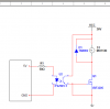
You want your circuit to resemble the attached. The way you have it drawn the MOSFET Gate is shorted to ground. Also your U2, when it is turned on effectively becomes a 36 volt short to ground. The LED side of the opto will work fine with a fwd current of 10 mA and a fwd voltage of about 1.2 volts. That would be about a 380 ohm series resistor. I used 330 as a common off the shelf part.
This is your opto coupler data sheet. It's actually a quad so you might want to rethink that.
There may be a few other errors, I did not really look close at the MOSFET data sheet. Getting late for me as I am up at about 3:30 AM so you have a good evening.
<EDIT> OK, now I get the part numbers. I saw your comment about multi-sim. That makes sense. You are only working with the parts in the library that you have. </EDIT>
Damn, one more thing. With this setup the motor will run when the PIC output line is low. Look closely at what happens.
Ron

")