Continue to Site

Welcome to our site!

Electro Tech is an online community (with over 170,000 members) who enjoy talking about and building electronic circuits, projects and gadgets. To participate you need to register. Registration is free. Click here to register now.

  • Welcome to our site! Electro Tech is an online community (with over 170,000 members) who enjoy talking about and building electronic circuits, projects and gadgets. To participate you need to register. Registration is free. Click here to register now.

Model of LM331 for LTSpice

Status
Not open for further replies.
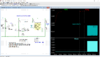
Yes, the only 1uF polarized cap is C2.
Noise suppression == C1
Attached V-F Theory of Operation
fritual

Will this work for you?
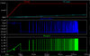
This is a transistor based model. I think this is a more practical simulation duration than 500uS.
If so I'll post the files.
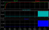
1599835607796.png


Clip from Logfile:
===================
.OP point found by inspection.

p6_p1: ix(u3:iout)=-5.00096e-008
t1: time=0.0316679 at 0.0316679
t2: time=0.0317147 at 0.0317147
per: (t2-t1)=4.67939e-005
freq: 1/(t2-t1)=21370.3


Date: Fri Sep 11 07:44:05 2020
Total elapsed time: 21.367 seconds.
=================================
 

Attachments

  • 1599835628188.png
    1599835628188.png
    463.8 KB · Views: 277
Last edited:
Ok...Here you go....let me know how it works out.
Attached my plot, leaving your schematic alone.
Since this is a TI part, can your LM331_Stand-Alone_V_to_F_Converter symbol and hierarchical data be used in their simulator?
I need to study SPICE directives, in your schematic, to prove it correlates to the *real* world.
fritual
 

Attachments

  • LM331_Stand-Alone_V_to_F_Converter_Test_fritual.jpg
    LM331_Stand-Alone_V_to_F_Converter_Test_fritual.jpg
    102.1 KB · Views: 233
Attached my plot, leaving your schematic alone.
Since this is a TI part, can your LM331_Stand-Alone_V_to_F_Converter symbol and hierarchical data be used in their simulator?
I need to study SPICE directives, in your schematic, to prove it correlates to the *real* world.
fritual

The model does not use any behavioral components so it should easily port over to another spice simulator.
Which TI simulator are you referring?

I have TINA and could the get the TI-PSpice simulator and port it over for you.
 
The model does not use any behavioral components so it should easily port over to another spice simulator.
Which TI simulator are you referring?

I have TINA and could the get the TI-PSpice simulator and port it over for you.
Hi,
TINA, which does appear to work using Wine.
Fout duty cycle shouldn't deviate much from 50%.
Attachment looks more like a noise spike, changing .parm IN=.125/Duration=120u.
Perhaps I don't have linear sweep setup correctly.
 

Attachments

  • LM331_Stand-Alone_V_to_F_Converter_Test_fritual2.jpg
    LM331_Stand-Alone_V_to_F_Converter_Test_fritual2.jpg
    183.8 KB · Views: 254
Hi,
TINA, which does appear to work using Wine.
Fout duty cycle shouldn't deviate much from 50%.
Attachment looks more like a noise spike, changing .parm IN=.125/Duration=120u.
Perhaps I don't have linear sweep setup correctly.


I don't see anywhere in the spec where Fout duty cycle is specified. The output pulse will be narrow and inverted. I don't think your allowing enough time for the output to settle. You can try ramping up the power supply over a few milliseconds.

If you want 50% duty cycle, I think you'll have to add a flip flop to the output and operate at half frequency or double the operating frequency. Its been awhile, but I have an LM331 on hand and guess I can build the VtoF again to verify.

Meanwhile, try this:

I've outlined the changes below.
1. I replaced C1 with an X7R cap over the existing one. The existing one had missing params. This is for the sim only...in real HW use a temperature stable cap like an NPO.
2. Removed "startup" directive. But now have to add IC statements.

1599876163813.png


Log file output:

p6_p1=0.035 FROM 0 TO 0.035
t1: time=0.0327774 at 0.0327774
t2: time=0.0331834 at 0.0331834
per: (t2-t1)=0.000405968
freq: 1/(t2-t1)=2463.25
 
Last edited:
Hi

This is a exert from the TI support forum:

Question from User:
"I made a voltage to frequency converter with the Lm331, but my problem is that i can't make the duty cycle 50/50. What i want is: when the input voltage on pin 7 increase: my Frequency increase to but the duty cycle stays 50/50. Also the optional offset doesn't work. "

Answer from Support Engineer:

"The LM331 utilizes an internal one-shot timer to provide the pulse output which doesn't support maintaining a constant 50 % duty cycle over an assigned V-to-F range.

The optional offset control circuit applied in the LM331 datasheet Fig. 14 should be usable. Possibly, the potentiometer resistance you are using is too high. Either try reducing the poteniometer resistance, or lowering the 22 k resistor to gain more adjustment range."
 
I don't see anywhere in the spec where Fout duty cycle is specified. The output pulse will be narrow and inverted. I don't think your allowing enough time for the output to settle. You can try ramping up the power supply over a few milliseconds.

If you want 50% duty cycle, I think you'll have to add a flip flop to the output and operate at half frequency or double the operating frequency. Its been awhile, but I have an LM331 on hand and guess I can build the VtoF again to verify.

Meanwhile, try this:

I've outlined the changes below.
1. I replaced C1 with an X7R cap over the existing one. The existing one had missing params. This is for the sim only...in real HW use a temperature stable cap like an NPO.
2. Removed "startup" directive. But now have to add IC statements.
Hi,
Symulation has shown Fout needs to be doubled and adding a FF. The maximum driving frequency I need must be limited to 25 khz and not deviate from 50% duty cycle. If you have any suggestions doubling the frequency, here is the formula: Fout = Vin * (Rs / 2.09 * RL * Rt * Ct).
Also, I only have ceramic capacitor's, so what's a good resource for NPO's?

Why do you need 25Khz? Why does it need to stay at 50%
Is this for audio application? How about sharing some back ground on your application?
 
The document implies that voltage-to-frequency is the only functional requirement. There doesn't appear to be a requirement for a fixed duty cycle.
Perhaps non-critical on state-of-the-art hardware, but attachment does cover max out/duty cycle, etc.
 

Attachments

  • D-A_Hardware.pdf
    32.9 KB · Views: 205
Perhaps non-critical on state-of-the-art hardware, but attachment does cover max out/duty cycle, etc.

Then you will have to use a flip flop at the output or use a different chip because the LM331 duty cycle varies and there is nothing in the TI spec that states the duty cycle.

1599943711290.png
 
Last edited:
Then you will have to use a flip flop at the output or use a different chip because the LM331 duty cycle varies and there is nothing in the TI spec that states the duty cycle.
I calculated ct to be 470pf, allowing accurate "strobing".
Please add this to your schematic, along with R4, before posting a visual.
. . . doesn't LTspice/TINA have a functional virtual frequency counter?
 
I calculated ct to be 470pf, allowing accurate "strobing".
Please add this to your schematic, along with R4, before posting a visual.
. . . doesn't LTspice/TINA have a functional virtual frequency counter?

No...it does not.
I could try pointing with the mouse in the waveform viewer but the .meas statements are more accurate.
The .meas statement results are in the log file. I've shown the results below the graph.

See below.

1599957370840.png


Log file:

p6_p1=0.035 FROM 0 TO 0.035
t1: time=0.0321685 at 0.0321685
t2: time=0.0323603 at 0.0323603
per: (t2-t1)=0.000191795
freq: 1/(t2-t1)=5213.89 <-Fout at V(out)
t1_q: time=0.0329358 at 0.0329358
t2_q: time=0.0333192 at 0.0333192
per_q: (t2_q-t1_q)=0.000383426
freq_q: 1/(t2_q-t1_q)=2608.07 <---Fout at V(Q)
 
Last edited:
No...it does not.
I could try pointing with the mouse in the waveform viewer but the .meas statements are very accurate.
Did you intensionally remove R4, 10 K resistor? TTL would have a fit with 9 volts!
The cap appears to double frequency, that calculations reported V-F out == 43,775 Hz, while simulation == 5,214 Hz ?
I've attached ZX schematic showing 'EAR' having R34, 220 ohm to ground and C10, 10 nF & R33, 4K in series, feeding pin 20 of IC1.
Could this FF load be simulated, too?
 

Attachments

  • zx-ear.pdf
    1.7 MB · Views: 203
Did you intensionally remove R4, 10 K resistor? TTL would have a fit with 9 volts!

Yes...you said nothing about TTL.....where did that come from?
So...use a different FF instead or level shift.

The cap appears to double frequency, that calculations reported V-F out == 43,775 Hz, while simulation == 5,214 Hz ?

That's exactly what that value will do, it will set the LM331 to 43khz. The FF output will be half that frequency at 50% duty cycle..
Since you've set the input to 0.125mv, both outputs will scale accordingly. The simulation is correct.

I've attached ZX schematic showing 'EAR' having R34, 220 ohm to ground and C10, 10 nF & R33, 4K in series, feeding pin 20 of IC1.
Could this FF load be simulated, too?

Sorry...but I don't see a FF in that schematic.

I think I'm done here. Maybe someone else here can help.
 
Last edited:
No...it does not.
I could try pointing with the mouse in the waveform viewer but the .meas statements are more accurate.
The .meas statement results are in the log file. I've shown the results below the graph.

See below.
Log file:

p6_p1=0.035 FROM 0 TO 0.035
t1: time=0.0321685 at 0.0321685
t2: time=0.0323603 at 0.0323603
per: (t2-t1)=0.000191795
freq: 1/(t2-t1)=5213.89 <-Fout at V(out)
t1_q: time=0.0329358 at 0.0329358
t2_q: time=0.0333192 at 0.0333192
per_q: (t2_q-t1_q)=0.000383426
freq_q: 1/(t2_q-t1_q)=2608.07 <---Fout at V(Q)
Only 1 '.meas' statement functioned correctly in fritual's LOG file:

p6_p1=0.035 FROM 0 TO 0.035
Measurement "t1" FAIL'ed
Measurement "t2" FAIL'ed
Measurement "per" FAIL'ed
Measurement "freq" FAIL'ed
Measurement "t1_q" FAIL'ed
Measurement "t2_2" FAIL'ed
Measurement "per_q" FAIL'ed
Measurement "freq_q" FAIL'ed

Please help resolve the other 8 fail'ed '.meas' statements.

Post your LTspice schematic
 
Last edited:
Status
Not open for further replies.

Latest threads

New Articles From Microcontroller Tips

Back
Top