Provide your input signal level vs scale settings to use for tests. So we work from the same test values.
Please post your '.asy' battery symbol 'V1' you use in schematic . The LTspice mac version lacks it, along with tool bar/ help menu.
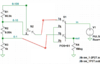
Also, is there a part number/visual for rotary switch S1?
1) R8=1k, R7=9.09k, R5=90.9k (1% metal film)
0-1v scale, .125v DC sig:
p6_p1=0.035 FROM 0 TO 0.035
t1: time=0.0321415 at 0.0321415
t2: time=0.0323274 at 0.0323274
per: (t2-t1)=0.000185933
freq: 1/(t2-t1)=5378.28
t1_q: time=0.0328846 at 0.0328846
t2_q: time=0.0332561 at 0.0332561
per_q: (t2_q-t1_q)=0.000371491
freq_q: 1/(t2_q-t1_q)=2691.85
0-10v scale, 1.25v DC sig:
p6_p1=0.035 FROM 0 TO 0.035
t1: time=0.0321107 at 0.0321107
t2: time=0.0322966 at 0.0322966
per: (t2-t1)=0.000185896
freq: 1/(t2-t1)=5379.34
t1_q: time=0.032669 at 0.032669
t2_q: time=0.0330415 at 0.0330415
per_q: (t2_q-t1_q)=0.000372448
freq_q: 1/(t2_q-t1_q)=2684.93
0-100v scale, 12.5v DC sig:
p6_p1=0.035 FROM 0 TO 0.035
t1: time=0.0321046 at 0.0321046
t2: time=0.0322909 at 0.0322909
per: (t2-t1)=0.000186302
freq: 1/(t2-t1)=5367.63
t1_q: time=0.0326635 at 0.0326635
t2_q: time=0.0330357 at 0.0330357
per_q: (t2_q-t1_q)=0.000372244
freq_q: 1/(t2_q-t1_q)=2686.41
2) Divider values have increased by a factor of 10, in hopes of less loading on testing device
R8=10k, R7=90.9k, R5=909k (1% metal film)
0-1v scale, .125v DC sig:
p6_p1=0.035 FROM 0 TO 0.035
t1: time=0.0321396 at 0.0321396
t2: time=0.0323254 at 0.0323254
per: (t2-t1)=0.000185809
freq: 1/(t2-t1)=5381.87
t1_q: time=0.0328827 at 0.0328827
t2_q: time=0.0332541 at 0.0332541
per_q: (t2_q-t1_q)=0.000371394
freq_q: 1/(t2_q-t1_q)=2692.56
0-10v scale, 1.25v DC sig:
p6_p1=0.035 FROM 0 TO 0.035
t1: time=0.0321531 at 0.0321531
t2: time=0.032327 at 0.032327
per: (t2-t1)=0.000173884
freq: 1/(t2-t1)=5750.96
t1_q: time=0.0328487 at 0.0328487
t2_q: time=0.0331965 at 0.0331965
per_q: (t2_q-t1_q)=0.000347771
freq_q: 1/(t2_q-t1_q)=2875.45
0-100v scale, 12.5v DC sig:
p6_p1=0.035 FROM 0 TO 0.035
t1: time=0.0321491 at 0.0321491
t2: time=0.0323219 at 0.0323219
per: (t2-t1)=0.000172831
freq: 1/(t2-t1)=5785.99
t1_q: time=0.0328412 at 0.0328412
t2_q: time=0.0331871 at 0.0331871
per_q: (t2_q-t1_q)=0.00034586
freq_q: 1/(t2_q-t1_q)=2891.34