Electro Tech is an online community (with over 170,000 members) who enjoy talking about and building electronic circuits, projects and gadgets. To participate you need to register. Registration is free. Click here to register now.
Welcome to our site! Electro Tech is an online community (with over 170,000 members) who enjoy talking about and building electronic circuits, projects and gadgets. To participate you need to register. Registration is free. Click here to register now.
I don't know why you have two audio balance pots. If you use only one audio balance pot then it could be a dual pot so one part can do the audio balance and the other pot can apply the variable DC to the LM3914.
If you have two completely separate audio balance pots and if each is a dual pot for the variable DC voltage to the LM3914 then you need the switch to be a TPDT (3 poles) so it can switch the selected pot to the LM3914.
ohh ok the reason there are two audio pots is that there are two channels.
Like if the footswitch is up then channel a will have Audio Pot a which will also control the input for the IC. If the footswitch is down channel b is now Audio Pot b and control the input for the IC.
Each Pot will control an Audio and the input to the IC.
I think using the word channel isn't helping my situation really.
Basically player plugs in the guitar (mono)....then the sound gets split into left and right by the Pot. And the position of the pot (left to right) is displayed on the led's. Then if the player pushes the footswitch the OTHER pot is now being used to split the sound to left and right, and is also being used to control the display.
yeah its so that lets say I'm playing all on the right...then I can switch over to either center or the other side...it just leaves more options for me.
Yep I know i need two Dual Pots...but why a Triple Pole? 1 Pole for Audio and 1 Pole for the power to the LED's and IC signal input (ie: goes through the resistor to the signal input).
The first pole switches the audio between the two pots.
The second pole applies power to the LED that indicates which pot is selected.
The third pole switches between the sliders of the pots to the LM3914.
The third pole cannot light the indicator LED. It is a variable voltage that is too low to light an LED.
Right ok so I can't have it with my method of having the 3.3333V for Rhi or maybe 9.9999? And then feeding 9V to the Pot in parallel with the indicator LED.
Your saying that I should hook it up so the Pot is getting 1.25V from pin 7 (I think) and using that across the potentiometer with the wiper going to a switch?
(I'm sorry about asking a bunch of probably annoying questions I'm just trying to understand this all fully)
You can make the pin 7 any voltage from 1.25V and up. But the circuit works well and is the easiest with it at 1.25V.
You don't want to mess up pin 7 with additional current from the indicator LED.
Ok that makes more sense now. I assume TPDT pots are common?
Also let me just run this by again:
-1.25V to one side of the Pot
-1/9th the Pots resistance Resistor followed preceded by switch to Wiper and Signal In.
-Small resistor to the other side of Pot to ensure first light is on?
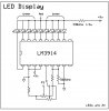
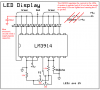
Ok so this is how you recommended to setup the IC correct?
Also since all those resistors are in parallel with the 560ohm won't I have to adjust it's value so that the total resistance among all those resistors are 560ohm?
Ok so this is how you recommended to setup the IC correct?
Also since all those resistors are in parallel with the 560ohm won't I have to adjust it's value so that the total resistance among all those resistors are 560ohm?
1) You don't need the 330 ohm resistor in series with the LEDs because the LM3914 regulates the current in the LEDs.
A resistor is needed if the IC is in the bar mode and many LEDs are lighted then their total current is high which would cause the IC to get too hot.
2) Every electronic circuit should have a supply bypass capacitor.
3) The resistors and the 10k resistance of pin 6 are in parallel with the 560 ohm resistor creating a total resistance of 510 ohms. Then the LED current is 12.5/510= 25mA.
I think I calculated the resistors so that the 1st LED lights when the selected pot is at minimum and the 9th LED lights when the pot is at max. Then the middle LED will light when a pot is in the middle.
I was just wondering why every circuit needs a supply bypass capacitor. Also how would I go about calculating the needed value. (I'm thinking it has something to do with the current or voltage.) Does this also mean I will need one for the Indicator circuit? Or will this act for both?
Also could I not have just adjusted the 560ohm resistor so that the current was still 22ma. I'm not going to but I'm just wondering.
This site uses cookies to help personalise content, tailor your experience and to keep you logged in if you register.
By continuing to use this site, you are consenting to our use of cookies.