Continue to Site

Welcome to our site!

Electro Tech is an online community (with over 170,000 members) who enjoy talking about and building electronic circuits, projects and gadgets. To participate you need to register. Registration is free. Click here to register now.

  • Welcome to our site! Electro Tech is an online community (with over 170,000 members) who enjoy talking about and building electronic circuits, projects and gadgets. To participate you need to register. Registration is free. Click here to register now.

LM3914 Balance - Dot Mode

Status
Not open for further replies.

TrevorP

New Member
Hey Everybody,

Since my last project in November (which failed horribly), I haven't really encountered something that I think I can handle in terms of my skill level.

Anyway here's the idea:

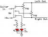
It's essentially a balance pedal for Guitar, as you rotate a potentiometer the position of a dot moves depending on if the sound is moving left or right.

The problem is that the LM3914 drives 10 LEDs...which means that when the pot is entirely open that the 10th one would be on. But I want it so that it only drives 9 LEDs and the 5th one would be when the pot is in the center.

Any ideas? I've attached what I have so far. I believe that the power supply doesn't have the proper "automatic" battery takeover that I want but I'll most likely just be using a wall-wart for power.

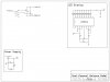
UPDATE: August 8th. New Schematic uploaded. (smaller image too). Still not sure about the trickle-charger but I made an educated guess that that is how it works.
 

Attachments

  • Balance Dot.jpg
    Balance Dot.jpg
    441.5 KB · Views: 323
Last edited:
I'm thinking that I might be able to achieve the desired 9 led usage by using the voltage divider that is before it. But I'm not quite sure yet.
 
I am confused on too many levels.
Are you wanting a simple “balance” control that pans left to right?
Do you want two balance controls that are switched by a foot switch?
When I understand that you are after we can fix the audio area.

Loose the resistor in you power supply area.

The dot graph area is very doable. I will get back to that when I have more time.
 
ronsimpson said:
I am confused on too many levels.
Are you wanting a simple “balance” control that pans left to right?
Do you want two balance controls that are switched by a foot switch?
When I understand that you are after we can fix the audio area.

Loose the resistor in you power supply area.

The dot graph area is very doable. I will get back to that when I have more time.

Yes a simple balance control of which there will be two options, activated by the footswitch.

I know that the power supply is wrong...for some reason I thought I needed a resistor there for trickle charging.
 
1) An audio balance contol pot must be linear not log. Then the sound volume will be equal on both channels when the control is centered.
2) You have two audio balance contols with a switch. Why two?
3) If you use a dual pot then one section could contol the audio balance and the other section could be the pot in the LM3914 schematic.

Your trickle-charge resistor is connected to trickle discharge the battery.
 
1) Thanks, I wasn't sure of this.
2) The idea is that the switch allows you to change between two balance control pots. I probably should have just added that later after getting down the basics.
3) Yep the idea is that it will be a dual pot (I couldn't think of the right word), and it will act exactly as you said.

I'm aware that the power supply has problems I just hadn't removed that part yet. I'm thinking of just not using a battery at all.
 
Dot Graph IC. LM3914
1K Resistor pin 7 to ground to set LED brightness.
Pin 4,8 to ground.
Connect Pin 7 to 6
Linear pot from pin 6 to pin 4 with wiper arm to pin 5.
The voltage on pin 6 is the voltage for the top LED. The voltage on pin 4 is the voltage for the bottom LED. The wiper will travel from the voltage on pin 4 to the voltage on pin 6.

Use two (dual) linear pots.
 
Ok I understand how the whole reference thing works...

So if lets say my max voltage through 5 was 3V. Then in order to make it so that the pot was only using 9leds and NOT 10 then I would have to make the pin 6 input as 3.333333V. Correct?
 
I think the way I wired the LM3914 there will be 1.25 volts across the pot. It really does not matter in this case. Go to National’s web and get the data sheet on the 3914. There are 10 or 11 resistors from pin 6 to pin 4. This sets where each LED turns on. If you connect the pot across pins 6 to 4 then all 10 LEDs will be spread across the full rotation of the pot. If you want 9 LEDs to be spread evenly across the pot then we need a way of having 90% of the voltage across the pot. (example: use a 100k pot. Disconnect the pot from pin 6. Add a 10k resistor from pin 6 to the pot. Now the voltage is across 110k ohms. The pot will have 90% of the voltage. Now the top of the pot will only light LED-9.)

Now that I think about it you may not like where LED-1 comes on. You may need to add 10K to the ground end of the pot to move up where LED-1 comes on.
 
On there Datasheet it says that VRef Out = 1.25(1 + R1/R2) ... does that current go INTO Ref Hi (pin 6)?

Basically is that the voltage at which will be the top led?

EDIT: If so then if I make it so that the max voltage applied from the pot can be 3V (this makes it easier to drive channel indicator LEDs), then I would want 3.3333V at VRef Out at pin 7, also 1k is reasonable for LED brightness so:

3.333V = 1.25(1 + 1000/R2)

R2 = 600ohms

Correct?
 
Last edited:
The voltage is not important. You can leave R2=0 and the voltage will 1.25 volts. This voltage sets the high LED. It does not effect the voltage across the LEDs. You can use LED that turn on at 1.5 to 3.3 volts and it does not mater where the ref voltage is.

You do not need to make 3 volts. Use the REF out voltage for the POT. That voltage can be 1.25 to 5 volts it does not mater. If the pot is (more or less) from RLO to RHI then where the pot is set to will light one of the LEDs. You can use R2=0 to 1k and the same LED will be on.
 
Hey I guess I just don't quite understand what you are saying.

https://www.electro-tech-online.com/custompdfs/2007/08/LM3914.pdf

In that on page two the Ref Out is attached to Ref Hi. Meaning that whatever the voltage is across those two resistors is going to be the voltage that lights the 10th LED. There are also a few formulas given for setting that Ref Out Voltage and the current that each LED will receive.

So what I don't understand is why my method WONT work since the signal voltage determines what LED will be lit at that time and those formulas say how to set up the range of voltages for the LED's.
 
Simply connect pin 6 to pin 7 so that Rhi is Vref. Then connect pin 8 to ground so that Vref is 1.25V.
Measure the total resistance of your pot and add a resistor to its top pin that is 1/9th its resistance. Connect the free end of this resistor to Vref, connect the slider to pin 5 of the LM3914 and connect the low pin of the pot to ground.

Then with the pot set to minimum no LED will light, with the pot set to half then the 5th LED will light and when the pot is at max then the 9th LED will light.

Connect another resistor in series with the low pin of the pot then to ground so that the 1st LED will light with the pot set to minimum.
 
Edit: Also isn't the Iled = 12.5/R1. So without an R1 it would be 12.5amp...? Enough current for an led? I think you need a resistor from pin 7 to ground in order to limit the current of the led.
 
Last edited:
Of course you must have R1 from pin 7 to ground to set the LED current. Use 560 ohms for 22mA in each LED. The 10k Rhi to Rlo divider increases the current to 23mA.
 
Right so 560 ohms for R1. It's just that based on the need for 3V for the channel indicator leds. I'm wanting to use that same 3V that the leds are getting and making that the signal voltage BEFORE going into the Pot. Then whatever voltage is left over after going through the Pot will be the signal voltage. And since there will be NO led's lit up at 0V or max resistance then there must be a small resistor before the pot.

9V -> Voltage Divider -> 3V -> Channel LED to ground. in parallel with -> small resistor -> Potentiometer -> signal in.

EDIT: See updated diagram to see what I mean. (i forgot the small resistor for infront of the POT)
 
Last edited:
The LM3914 has regulated current drivers for the LEDs. With a 5V supply, the LEDs can be 2V red ones or 3.5V blue ones and the LM3914 provides a regulated current that is set by R1. If the supply voltage is much too high then the LED driver transistors inside the LM3914 get hot. Then the LM3914 will overheat if it is set to the bar mode and many LEDs are lighted at the same time.

The LM3914 has an accurate Vref that is probably more accurate than your supply voltage so you might as well use it as the reference voltage for the LED trigger voltages and for your pot.
 
Ok I can see how I would rig up that Pot along pins 4 5 and 6...but as one of the features of this circuit there will be two leds of which one will lit up indicating which "channel" or pot is being used at the time. And using only a DPDT I can't see where I would put the indicator LED's so that they would have current. Would they be able to be driven by the 1.25V? I was under the impression that most led need like 2+ V to work.
 
TrevorP said:
one of the features of this circuit there will be two leds of which one will lit up indicating which "channel" or pot is being used at the time. And using only a DPDT I can't see where I would put the indicator LED's so that they would have current. Would they be able to be driven by the 1.25V? I was under the impression that most led need like 2+ V to work.
You are using only half of the switch to switch the audio. Use the other half of the switch to light one of the two LEDs.

You are not switching two LM3914 circuits so you don't want to connect the two LEDs there.

Leds work with current, not voltage. An LED needs a resistor in series with it to limit the current or it might blow up.
 

Attachments

  • balance contols.PNG
    balance contols.PNG
    21.5 KB · Views: 192
There is only 1 LM3914. The switch changes which Potentiometer is going to be the input for it and the Indicators. (see my schematic)
 
Status
Not open for further replies.

Latest threads

Back
Top