Continue to Site

Welcome to our site!

Electro Tech is an online community (with over 170,000 members) who enjoy talking about and building electronic circuits, projects and gadgets. To participate you need to register. Registration is free. Click here to register now.

  • Welcome to our site! Electro Tech is an online community (with over 170,000 members) who enjoy talking about and building electronic circuits, projects and gadgets. To participate you need to register. Registration is free. Click here to register now.

LM3914 with a buzzing relay

dobbsincrete

New Member
I am building a 5v humidity control for my bathroom extractor fan.
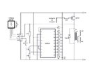
The circuit, (image attached), is based on information I have read on the internet and uses an LM3914, an led bar graph, a transistor and a 5v relay. The humidity sensor I have is the Velleman mm102. Seemed like a nice little project, but …..
I am having a problem with the transition between the LM3914 outputs.
As the humidity level changes, and the selected led level comes in to play, the transition, if slow, causes the transistor to not switch cleanly. This then makes the relay buzz briefly and the contacts not operating or releasing cleanly.
Does anyone have a way around this please?
Any help or guidance would be much appreciated.
Thank you
Fan Control.jpeg
 
First, interesting use of a LM3914.
Try removing the 22k resistor at the base of the transistor (or changing it to a 1k). The current into the chip is already limited by the voltage divider on pins 8 and 9 on the chip. No need to further restrict current flow from the PNP base.

Current at each LED current sink is calculated from the R2 R1 voltage divider

1704328119994.png
Also, the LED ties the sink to 2 or 3 volts from + supply so you may want to remove the LED as some of the current will flow through the LED and some from the PNP base.
 
Last edited:
Your LEDs will be a bit of a problem as suggested by ZZO.
You could try replacing the LEDs with 10k resistors, this will give a much greater voltage swing, more like five volts that two volts.
Look what I did in this old project:


As for the chattering relay, maybe use something like a 555 as a timer.
When the signal from the 3914 goes to the OFF state, the 555 holds the relay ON for a few seconds.

JimB
 
Internally, the 3914 (and 15, and 16) is a stack of 10 voltage comparators. Unfortunately for you, there is no hysteresis around any of them. The part is intended to drive LEDs with a (relatively) rapidly changing signal, where retinal persistence hides any brief flickering between outputs.

One solution is to drive the relay with the output of a flipflop. For example, if the Set and Reset are connected to outputs 6 and 4, then the fan would come on at humidity level 6, but not turn off until the humidity had dropped down to level 4. The flipflop can be 1/2 of a CD4013, or two gates in a CD4093 package.

To prevent exceptionally high noise from causing relay chatter, add a capacitor from the sensor pot wiper to GND.

ak
 
Also, the voltage divider at pins 6, 7 and 8 are trying to set a voltage of 5,3v when your Vdd is only 5V so that may be causing some slow switching. The footnote on the datasheet says the maximum VRef should be 1.5v below supply voltage. I think the switching of an LM3914 is fast but the current to your relay is so low that you see chatter. See below...

Even more problematic is the case if you have a red LED with a Vf of 2V. The base - emitter voltage .0.6V so, your base current will be only 63ųA and, with an Hf specified in the very broad range of 150-800, you could have as little as 0.063mA x 150 = 9.5mA from your transistor.

Look up the switching current on your relay's coil. Likely well over 9mA. You may be lucky enough to have a transistor with a bit more gain and close to your relay's switching current (and it likely is because you're getting some slow switching.

First, fix the voltage divider. Change the 1.2k to 2.4K (by simply adding a second 1.2k resistor in series with the original).

Then try replacing the 22k base resistor with a 1k and see if your switching improves.

If not good enough, remove the LED from the pin you use.
 
Thank you all for your replies.
As I have the led bar graph in a socket it was quick and easy to remove it. Unfortunately removing the led's did not fix the problem, so I am about to attempt some of your other suggestions. Thanks again.
 
You could try connecting a high value resistor from the transistor collector back to the IC input pin?

eg. Try 470K? That should hopefully add just enough hysteresis to avoid the jitter, without changing the bar graph reading too drastically?
 
Once again thank you for all your replies and suggestions.
So far then, I have replaced the 22k resistor for the 1k. I have changed the voltage divider from 1.2k to 2.4k and finally added a 560k across the collector of the transistor and 10k wiper. Sadly, at each mod, with led's both in circuit and out, there is no noticeable difference to the unclean switching (buzzing) of the relay - albeit briefly.
Interesting to note though, the voltage on the input to the 3914, from the sensor wiper, is only about 0.03v (between 2.22v and 2.25v) where this brief transition issue happens - both with the humidity rising and falling.
As suggested by AnalogKid, a flip flop maybe the best way to go, or even a Schmitt, to give the clean 'relay click' I am looking for. (may need some advice on that one though!)
My worry with what I have at the moment is that the bathroom extractor fan has a built-in timer which could be affected by the unclean mains switching on/off.
Thanks again
 
Power supply
what is your power source? Is it strong enough to trigger the relay (without the circuitry)?

Relay
Is your relay clearly labelled to trigger with a 5VDC supply?

Transistor
Are you sure your transistor is connected correctly? The BC-series pinout...
1704573731568.png
 
So far then, I have replaced the 22k resistor for the 1k. I have changed the voltage divider from 1.2k to 2.4k and finally added a 560k across the collector of the transistor and 10k wiper.

Try lower values than 560K - without knowing the exact impedance at the input (source and pot setting) that was just guesswork.

eg. 220K, 100K ??
A low enough value should hopefully give a clean "latch" effect, though lower values will also cause more of an offset in the display LED position.
 
Thank you again for all of your support and suggestions for my humidity control project,
The power supply is an independent, mains driven, 5v supply capable of providing in excess of 1amp. The relay is a 5v Finder relay with 6amp mains contacts.
Thank you too to rjenkinsgb for your suggestion. I have replaced the 560k with a 100k and the transistor/relay appear to now be working fine. Interestingly, as the lm3914 transitions between the output levels, there is still ‘fade’ between the led’s apart from the selected level that is set to switch the transistor and hence the relay - picture of controller attached - thanks again,
IMG_2124.jpeg
 
I am building a 5v humidity control for my bathroom extractor fan.
The circuit, (image attached), is based on information I have read on the internet and uses an LM3914, an led bar graph, a transistor and a 5v relay. The humidity sensor I have is the Velleman mm102. Seemed like a nice little project, but …..
I am having a problem with the transition between the LM3914 outputs.
As the humidity level changes, and the selected led level comes in to play, the transition, if slow, causes the transistor to not switch cleanly. This then makes the relay buzz briefly and the contacts not operating or releasing cleanly.
Does anyone have a way around this please?
Any help or guidance would be much appreciated.
Thank you
The outputs of the LM3914 are designed to slightly fade in and fade out. That is causing the the relay to chatter.

Remove the 22k resistor (Pin current is limited to ~10mA anyway). Change 100k resistor to 1k.
Connect the BC557 base to the cathode of LM3914 pin you want to energize the relay. Make sure you are using a 5v relay.

If this doesn't work (I think it will) try removing the relay snubber diode and connect a small capacitor (trial and error-maybe 47u) across the relay coil. The cap will cause a small delay each time the relay
de-energizes..

oops--didn't see post #12.
 
eTech, thank you for your reply. Please can I confirm your suggestions.
I have already replaced the 22k with a 1k between the selected output led and the transistor base (#2, #5), should I not have a resistor here at all?
Also, should I revert the voltage divider to a 1.2k between pins 6/7-8 as I have a 2.4k at the minute (#5)?

I suggest an R1 value of 1.21k, so the max limit is ~10mA each output pin.
Re-thinking a bit, the current will split between the LED and transistor base, so I suggest the 22k base resistor could be reduced to 510 ohms, and the 100k resistor reduced to 2k. That would provide about 2mA to drive the base of the PNP (providing plenty of relay drive current), and 8mA for the LED.
 
Thank you eTech.
Just a query though on your last suggestion. You say to reduce the 100k to a 2k. Is this the resistor across the transistor emitter, or the new one (#11) between the collector and the LM3914 input?
 
Many thanks for the help you have all given me with a project that I thought looked so simple!!
I have taken into account your suggestions and have ended up with the circuit attached which seems to work albeit using a light bulb in place of the fan (currently a bit cold upon the loft).
I enjoy building electronic projects but not a designer so once again thank you.
Fan Control.jpeg
 
You need to add a base-emitter resistor to the transistor; eg. 4K7 or 10K

Without that, there is no absolute guarantee that the base feed (a LED output) will be held near enough 5V to avoid some current through the transistor.

The output is only pulled up to the LED conduction threshold, which could be a volt or more.
 

Latest threads

New Articles From Microcontroller Tips

Back
Top