Hi,
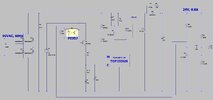
Please advise how to prove stability for the attached TOPswitch-HX (TOP255GN) Flyback which operates in Continuous Conduction Mode
It is with 90VAC input and 24V, 0.8A output.
I calculated the feedback loop Bode plots using AN-57 by Power Integrations.
However, the Bode plots come out as nonsense. They give a crossover frequency of 11600Hz. This is above 10% of the switching frequency, and 33% of the RHPZ. -And yet the converter shows perfect stability, even when no_load_to_full_load transient.
I calculated the Power Stage transfer function using equations 9,10,11,12,13 and 15 from AN57.
I calculated the “Error Amplifier & Modulator” transfer function using equations 20,21,22,23 & 24 from AN57.
The Calculated Bode plots and schematic are as attached.
_ _ _ * * * _ _ _
Concerning AN57..
*..What equation would you use to calculate the Q in equation 15?
I used 1/R * SQRT(Ls/Cout)
Where Ls = secondary coil inductance
R = Secondary coil resistance + output capacitor ESR (ESR of cap at crossover frequency).
*..What value would you give for “open loop gain of TL431” (KTL431), in equation 23?......I used 562.
*..What value would you give for “KTOP” in equation 22?......i used 0.2.
*..What value would you give for “KOPTO” in equation 24?, ..given that the opto is in Darlington connection with the NPN…..i used a value of 40.

