Some circuits oscillate without one.TrevorP said:I was just wondering why every circuit needs a supply bypass capacitor.
A battery has an internal resistance that increases as it runs down. Then the supply voltage changes as the load current changes. A supply bypass capacitor smooths the voltage changes so they don't change sharply and the change is much less. The capacitor powers the circuit when the battery can't.
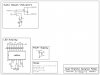
If you have only one battery then your circuit needs only one supply bypass capacitor. If it has RF then a ceramic disc capacitor must also be used since it works well at RF frequencies and an electrolytic capacitor works well at low frequencies.Also how would I go about calculating the needed value. (I'm thinking it has something to do with the current or voltage.) Does this also mean I will need one for the Indicator circuit? Or will this act for both?
A very low current low frequency circuit needs 0.1uF to 10uF.
A "medium" current low frequency circuit needs 100uF to 1000uf.
A high current low frequency circuit needs a high capacitance.
If the 560 is changed to 620 ohms then the LED current in the circuit with the pots is 22mA. The max current for most LEDs is 30mA to 40mA. You won't notice any difference between an LED at 22mA and another at 25mA. Double the current is only a little brighter because your vision's response to brightness is logarithmic (before your iris appies its automatic brightness control).Also could I not have just adjusted the 560ohm resistor so that the current was still 22ma. I'm not going to but I'm just wondering.