Continue to Site

Welcome to our site!

Electro Tech is an online community (with over 170,000 members) who enjoy talking about and building electronic circuits, projects and gadgets. To participate you need to register. Registration is free. Click here to register now.

  • Welcome to our site! Electro Tech is an online community (with over 170,000 members) who enjoy talking about and building electronic circuits, projects and gadgets. To participate you need to register. Registration is free. Click here to register now.

LM2917 Tachometer for V12

Status
Not open for further replies.

alexb1406

Member
Hi folks, hope someone can help me. The rev counter on my 1973 Daimler V12 has given up the ghost and the chip (I'm assuming that is the fault) is unidentifiable - the numbers on it are MIC 7303 (Smiths instrument). Does anyone know anything about this?

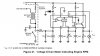
I have now decided to try to make my own. First I tried using a 555 monostable but the signal from the coil is too erratic and I found it difficult getting the needle steady. Now I'm trying with a LM2917 using the circuit below (taken from Texas Instruments data sheet) but it breaks down above 540Hz - on a V12 that's 5400RPM. Although the car rarely gets driven at those speeds I would like it to work reliably up to minimum 7000RPM (fsd). Is that the frequency limit for the LM2917?

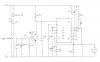
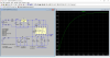
I have tried playing around with some of the resistor values but they don't have much effect. I am still testing it on a breadboard using a square wave oscillator - still have to try it on the car with the coil signal. The ignition is electronic but the tach signal behaves like a points system with 60 or 80V spikes.
 

Attachments

  • 2017-06-22_232356.jpg
    2017-06-22_232356.jpg
    43.1 KB · Views: 861
The LM2917 is spec'd well about 540 Hz.
upload_2017-6-22_20-11-4.png


Are you sure you have the right RC values? Can you use your pick-up on just one cylinder?

John
 
Thank you both for your input.

Reply to Mike: that's the version I tried but the coil signal was too wild. The monostable time had to be very short to allow frequency to increase to 700+ Hz without the output on-time overlapping. Then, at low RPM the coil oscillations caused double triggers of the monostable. Don't know if this may have affected it but I didn't have a 5v zener so I used a 1N4001 on the supply voltage to avoid over-voltage spikes. I was also running it directly from the 12v ignition instead of 9v - I used a 15v P6KE supprssor - but if it worked I would have probably used a 9v regulator such as a 78L09. I even tried setting up a Schmitt trigger on the input so it only caught the first big spike but again the needle wasn't steady so I gave up after that. Ironically, the opinion on that thread was that the LM2917 was better!

Reply to John: I hadn't seen that spec but you're right, it should work well above the frequency I need. I have to admit I'm a bit of a beginner at this so can you suggest some suitable RC values - and which ones? Is it the ones connected to pins 2 & 3? And I really want to use the original pick-up without adding extra wiring to the car. As you probably know 0.02uf does not exist so I used 0.022uf instead. Also, instead of a 470 resistor I used two 1k in parallel. Could this have affected the performance so much?
 
Your posted schematic doesn't show decoupling capacitors. Those are typically used between the power pin and ground to remove noise from the supply voltage. Depending on how much noise and how sensitive the chip is, you may see just one (e.g., 0.1 uF) or a decade series (e.g., 1.0 uF, 0.1 uF, 0.01 uF). They are important for the 555 too and are sometimes not included in "typical" designs because "everyone" knows to include them.

John
 
Thanks John - yes I did put something there close to the chip but I think it was a much higher value than you suggested - either a 4.7uf or possibly even a 100uf electrolytic. Is that too much?

I've just tried the LM2917 on the car and I can't get it to do anything - (so far I have ony been testing it on the bench with an oscillator signal). I have noted however on the oscilloscope that the tach signal from the ign amp only drops to around 2v, and on reading the datasheet it says that the threshold level can be set, I think on pin 11 if I understand it correctly, but I can't find any information on how to do this. Is it just a matter of applying a voltage divider with two resistors, e.g. 3.3k and 10k on to pin 11? Will that set it to around 3v?
 
In the schematic you posted, the diode and resistor (10 k) on Pin 11 effectively set the threshold of the comparator at 0.7 V. A voltage divider there could work. You could also add 1 or 2 additional diodes to get a greater drop or just use a zener diode at whatever voltage you want. I might try three diodes in series first to see if that is the problem as you probably have some laying around. The problem with a voltage divider is that when the source voltage drops, so will the output of the divider. Of course, that may not be a problem if everything is proportional.

The datasheet makes a point that neither input should go negative with respect to ground:
It is very important that an input not go below ground without some resistance in its lead to limit the current that will then flow in the epi-substrate diode.
That can be done with a Schottky diode with its + side (anode) connected to ground. and its negative-end to the pin. Thus, if the input to the pin goes more than about 0.3 V below ground, the Schottky diode will conduct and clamp the voltage from going more negative. That safety may not be necessary and is not shown in the circuit you are following because of the high resistance (10 k) in series.

John
 
Ok thanks John, I'll try the three (or four) diodes in series - if that works I'll go the zener route.

And oops! I bypassed the 10 and 20k resistors when I was testing on the bench and forgot to replace them! I did however put a 1N4007 between the input and V+. Strangely that enabled me to go to around 750 Hz before the output dropped - I don't understand why, it hasn't solved the problem but I've accepted it as it's enough for what I want.

It's evening here in the UK now so I may return to this over the weekend.
 
If you end up with a zener, remember it is put in with an opposite orientation to the current diode(s). Zener diodes control voltage by making use of a low, reverse bias breakdown voltage. If forward biased, as is the current diode, a zener just acts like a diode.

John
 
John, yes of course - but I had to think about that for a minute!

MikeMI, that's one hell of a spike over 600v! But my signal is closer to the V(in) on your chart so I'm beginning to think I may get away with something similar from the diode onwards, and that will all fit inside the tach casing. Thanks for that - I'll have a play with it when I get back to the job.

Another thing I thought of doing is copying the input components from the original tach and looking at whether I can do anything with that signal - after all, it worked ok for over forty years without blowing the chip.
 
Well I finally got it working - thanks to both Mike and John. Firstly I tried picking up a signal from various points from the original board but none of them seemed to work, so I set up a switching transistor similar to the one that Mike suggested and the output signal from that on the oscilloscope was quite clean, so I fed it to the LM2917 and to my surprise it worked! I've attached my final circuit diagram below for reference. Any comments/improvements would be welcome.

Incidentally, I tried using a 78L08 regulator but, remember the problem with the output dropping off over 540 Hz? - I managed to get it up to 750 Hz by removing the 10k and 20k resistors on the input to pin 1 - but with the voltage regulated to 8v, the limit was back down to around 600 Hz. Could someone look at my circuit and maybe find the fault that would cause this?

At the moment I've set it up temporarily in the car on the bread board to see how it goes. If all goes well I will make up a board the same shape and size as the original with the VR in the right place to be accessible through the hole in the casing as it was designed.

Once again, thanks to you both.
 

Attachments

  • 2017-06-26_233858.jpg
    2017-06-26_233858.jpg
    34 KB · Views: 412
Hi

I think the internal zener regulator of the LM2917 is causing issues.
Try this version that doesn't use the internal regulator. The output is set to 1V=100Hz
but can be changed to whatever you need.

See attached.
 

Attachments

  • LM29077000RPMTach.png
    LM29077000RPMTach.png
    59.2 KB · Views: 390
Last edited:
Thanks, I'll try that when I order some more parts from my supplier - unfortunately I don't have any electronics shops close by so I have to mail order - but I have to admit I don't understand how the zener could affect the output in that manner. You must have gone into a lot of trouble duplicating my circuit exactly but I note you've omitted the 470Ω resistor on pin 9 - is there a reason for this or is it a mistake? Also, the 1μ cap on pins 3 + 4 has become 18μ.

I like the idea of a separate (47kΩ) resistor in series with the variable pot to avoid sending the meter off the scale presumably.

Hi

The 470 ohm dropping resistor is only required if you use the internal zener regulator. It helps the zener maintain regulation (regulation is about 7.5v).
The capacitor affects the amount of ripple voltage and response time. The ripple should be about 70mv using the 18uF cap.
The response time is the amount of time a new voltage reading takes to stabilize. If the response isn't satisfactory, you can lower this value but the ripple voltage will increase. The choice of value for this cap is a compromise between response time, ripple voltage, and linearity.

The pot is needed to calibrate the output voltage. Nominal is about 50k, so if the 10k pot is centered is should be close to the correct setting for 7v output.
BTW- I didn't know the required output voltage and just chose 1v per 100hz but it can be whatever you need.

Also....the datasheet has some good information on design requirements.

eT
 
Thanks eT, I understand it a little better now. I have a LM78L08 - would that be suitable? And will I still need the P6KE15A supprssor or does the LM78 take care of that?

And I don't know the voltage required is either - I just adjusted the pot till I got an accutate (as close as possible across the range) reading, checked against the scope.

I'll try out your suggestions when I get some time but it probably won't be this week. For now I'm enjoying telling people what the bread board with all these components does that is sitting on the centre console.
 
Thanks eT, I understand it a little better now. I have a LM78L08 - would that be suitable? And will I still need the P6KE15A supprssor or does the LM78 take care of that?

The LM78 doesn't have input protection, so I would keep the TVS diode, it protects against transients. I also added a 1N4007 diode at the supply input to help prevent reverse currents from entering the circuit. Regarding LM78L08, we need to know the circuits output voltage requirements before we can decide if its usable.

And I don't know the voltage required is either - I just adjusted the pot till I got an accutate (as close as possible across the range) reading, checked against the scope.

Do you have any info on the type of tachometer gauge your using? Voltage range, etc? The choice of frequency components is dependent on the supply voltage and full scale output voltage. We really can't proceed unless we have that info.

I'll try out your suggestions when I get some time but it probably won't be this week. For now I'm enjoying telling people what the bread board with all these components does that is sitting on the centre console.

Cool..good work!

BTW-I've updated the circuit in post #13 to include the TVS and input diode.
 
Thanks eT,

Do you have any info on the type of tachometer gauge your using? Voltage range, etc? The choice of frequency components is dependent on the supply voltage and full scale output voltage. We really can't proceed unless we have that info.
I'll have to get it back on the bench and run it to full scale and take a measurement. All I can say on the type of tachometer is that it is a Smiths gauge with RVC 4010/01 at the bottom of the dial face.

BTW-I've updated the circuit in post #13 to include the TVS and input diode.
That's excellent, thank you.

Incidentally, I took the car out for its first proper test run last night and I noticed that the needle didn't always respond smoothly with the changes in engine RPM. For instance, it seemed to stick at around 1500RPM and I could hear the engine speeding up by one or two hundred RPM but no movement in the needle, and then suddenly it would jump up to 1700 or 1800. It also happenned at other points on the scale, but was intermittent and hard to observe whilst driving. I'm suspecting a mechanical fault but I'm sure it didn't do it before when the original circuitry still worked, so could this be an electrical fault?
 
Dodgy connection/joint affected by vibration?
I suppose it's possible as it is all still on the bread board but I would have expected it to flicker on and off if that was the case. I'll have a closer look at it when I get it back on the bench.
 
Status
Not open for further replies.

Latest threads

New Articles From Microcontroller Tips

Back
Top