k7elp60
Active Member
There has been some discussion on LED’s in parallel. It is my sense that most experts recommend that LED’s not be connected in parallel that uses 1 current limit resistor for the x number of LED’s in parallel.
I would like to show the readers of this forum a couple of my projects that actually use high intensity LED’s in parallel with one current limit resistor for the parallel LED’s.
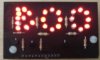
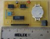
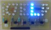
Both projects were built like name badges with the following dimensions 3.75” X 1.75” and each project consists of two circuit boards. The top board has the LED indicator and the transistor drivers, base resistors for the driver transistors and the current limit resistors. The bottom board has the electronics to flash the LED’s and the power supply. Both projects used 3V lithium coin cells for power. The first one I call the BOO badge as it was built for last Halloween used a CR2032, and the LED’s are multiplexed. The second project the LED’s just flash the different letters and are not multiplexed. Because I used blue LED’s the bottom board also has voltage pump that boots the voltage to 5V. The average current draw for the projects is as follows. Boo Badge 7mA, K7ELP badge 25mA. On the Boo Badge each letter of LED’s is split in 2 groups of LED’s in parallel with 1 current limiting resistor for each group, each current limiting resistor is 47 ohms. On the other badge each letter has all the LED’s in parallel with different values of current limiting resistors for each letter.
Both projects use CMOS IC’s
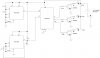
The schematic diagram of the BOO badge is also attached.
I would like to show the readers of this forum a couple of my projects that actually use high intensity LED’s in parallel with one current limit resistor for the parallel LED’s.
Both projects were built like name badges with the following dimensions 3.75” X 1.75” and each project consists of two circuit boards. The top board has the LED indicator and the transistor drivers, base resistors for the driver transistors and the current limit resistors. The bottom board has the electronics to flash the LED’s and the power supply. Both projects used 3V lithium coin cells for power. The first one I call the BOO badge as it was built for last Halloween used a CR2032, and the LED’s are multiplexed. The second project the LED’s just flash the different letters and are not multiplexed. Because I used blue LED’s the bottom board also has voltage pump that boots the voltage to 5V. The average current draw for the projects is as follows. Boo Badge 7mA, K7ELP badge 25mA. On the Boo Badge each letter of LED’s is split in 2 groups of LED’s in parallel with 1 current limiting resistor for each group, each current limiting resistor is 47 ohms. On the other badge each letter has all the LED’s in parallel with different values of current limiting resistors for each letter.
Both projects use CMOS IC’s
The schematic diagram of the BOO badge is also attached.