Continue to Site

Welcome to our site!

Electro Tech is an online community (with over 170,000 members) who enjoy talking about and building electronic circuits, projects and gadgets. To participate you need to register. Registration is free. Click here to register now.

  • Welcome to our site! Electro Tech is an online community (with over 170,000 members) who enjoy talking about and building electronic circuits, projects and gadgets. To participate you need to register. Registration is free. Click here to register now.

Help with Small Parallel LED Strings

glowlamp

New Member
Hello,

I would like to ask for a bit of advice on parallel LED strings.

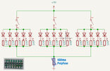
For the past few years, I've made the following circuit for some lights I make as part of my hobby.

I power either from a 5v usb adapter or from a 1.5v battery to 5v dc-dc board.

The strings go into tubes, glass, frosted plastic shapes etc.

I use small transfer board pcbs to hand solder different value 1206 resistors and solder each LED separately using wire wrapping wire or enamel wire.

Theres a picture of the transfer board to the bottom left of the attached picture (it's one from the junk bin - an early attempt at soldering years ago)

I generally have 3 individually switched strings. Each LED has a matched resistor depending upon its forward voltage.

This has worked fine and I have a little jig that allows me to quickly hold the 1206 resistors to the board for hand soldering.

I realise however this could be a lot better, and I think very dependent upon input voltage.

I though it might be better to have a small constant current driver for each string ?

Is there a simple way to do this. I would like to keep the circuit as simple as possible.

Also I would like the possibility of adding a high frequency PWM stage to one of the strings at a later date.

Any help appreciated :)
 

Attachments

  • led_parallel_string.jpg
    led_parallel_string.jpg
    67.6 KB · Views: 135
Depends of course how much current you want in LED string. And do you want
to stick with a 5V power supply, which would mean you need a boost converter
to power a serial string.

If you have access to higher V, and current in the 10's of mA, a simple current
regulator diode - https://www.mouser.com/datasheet/2/115/AL5809-767488.pdf
You just put the diode in series with the string. Or use -

1688382379924.png


Table helps you to figure out Vsupply you will need .

Vsupply = (Vcolormax x Number leds) + Vmin current regulator solution.


1688381200306.png


A real simple PWM can be done with ATTINY85 and a NPN transistor or N Channel MOSFET.

1688381628977.png


This was done with Arduino nano board ($3) to program the ATTINY85, and mBlock (free) used to develop code
for the program, real simple as you can see. The blocks in 3'rd window dragged out of second window, configed,
and then mBlock generates the Arduino code to put into the ATTINY85 via nano board.

1688381864879.png


Regards, Dana.
 
Last edited:
For your current circuit, about the only thing you can improve is to put pairs of the LEDs in series. This will improve significantly the efficiency of the circuit and extend battery life. As shown in the chart Dana posted, this will not work for all LED colors.

The LM317 constant current circuit works very well, but it requires a minimum voltage drop across it to work. This is true for all constant current circuits, but in your case a 5 V supply doesn't give you much voltage headroom to work with.

A solution is a classic 2-transistor constant-current circuit, something like this:

1688390591783.png


The headroom for this circuit is about as low as it can get, the Vbe of T1 plus the saturation voltage of T2. These add up to much less than the LM317 requirement.

Note that the 0.5 in the equation is correct. We are taught that the forward voltage (Vf) for transistors and diodes is 0.6 V to 0.7 V, but that is more the max Vf than the minimum Vf at which conduction begins. Conduction starts at a lower voltage. T1 starts conducting enough to draw base current away from T2 at a Vbe as low as 0.4 V in some small signal transistors.

ak
 
Many thanks for all the helpful replies :)

As a general question, apart from being inefficient.

Is the first circuit I posted that terrible ?

The reason I used that circuit was I was worried about a spike from a cheap usb charger (which someone might use other than the one provided ). Which why fry any microcontrollers - ( I do use Arduino with a transistor array in my own circuits )

Many thanks Matt.
 
I generally have 3 individually switched strings. Each LED has a matched resistor depending upon its forward voltage.

If you are individually selecting each LED R to match brightness thats not a bad method
to match brightness. Does not handle T and V changes, LED toi LED non linearity, but still
not bad. But tedious needless to say, picking all those R's.

Driving a series string with constant current is preferred method. Closer matching. But disadvantage
one bad LED takes out whole string, whereas parallel method can, for some cases, keep the rest of
the LEDs active. Depends on failure mode and impact on its series R.....

Your call.


Regards, Dana.
 
You can get MT3608 boost converters very cheap on lcsc, three of them and you can series all those LED's together. You'll add three very small inductors and some capacitors but wont need the switches, and have considerably higher efficiency.
 

Latest threads

New Articles From Microcontroller Tips

Back
Top