Continue to Site

Welcome to our site!

Electro Tech is an online community (with over 170,000 members) who enjoy talking about and building electronic circuits, projects and gadgets. To participate you need to register. Registration is free. Click here to register now.

  • Welcome to our site! Electro Tech is an online community (with over 170,000 members) who enjoy talking about and building electronic circuits, projects and gadgets. To participate you need to register. Registration is free. Click here to register now.

555 beep in bursts

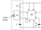
I'm trying make a non microcontroller circuit that gives about 5 quick beeps then roughly 1 second off, repeat. I'm running on 2 AAA batteries. I already have a bunch of cmos 555 on hand so was trying to make that work. I'm using a 3V active buzzer which is quite loud. I tried a few astable variations, the attached circuit with R1=1K (in series with variable resistor), R2=100K, C=10uF gave me the desired timing sequence but doesn't beep, just a steady on, 1 second off, repeat. What changes can I make to get the desired timing but with beeps.
Thanks,
Rich.
 

Attachments

  • 555 diode.PNG
    555 diode.PNG
    33.6 KB · Views: 65
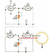
Here is the circuit in #18 re-worked to use 555's. Because of the high values of R1 and R2, these should be the CMOS version (LMC555, etc.).

A characteristic of both circuits is that the off time equals the total time for the beep burst. If you want the off time to be either longer or shorter than the beep burst time, the U1 circuit can be modified with the addition of one small-signal diode and another resistor. The orientation of the diode determines if the off time is longer or shorter.

Note that the CMOS 555 output can source only 10 mA. This should be enough, but if not there is a simple circuit change that drives the beeper when the output is low. In that state the output can sink 50 mA, more than enough for most piezo beepers.

Gated-Beeper-2-c.gif
 
This can be done easily with just two 555's, or with one quad gate package as in post #6. However, that circuit is for driving a bare piezo element, not a complete beeper. It uses two oscillators to make the beeper go on and off continuously, not in groups of beeps separated by off-times. However, the approach of one oscillator controlling another oscillator is correct.

BTW, CMOS logic circuits are extremely efficient, using only a few microamps to operate.

Either with two 555's or two oscillator circuits, have one oscillator drive the beeper at the rate you want the beeps to happen in a burst, such as five beeps in one second. The second oscillator gates the first one on and off. This sets the time between beep bursts. This type of gated beeper is pretty common, and uses very few parts.

Are you familiar with the CD4093? This is a quad NAND gate, but the gates have Schmitt trigger inputs. Not only do they work much better than a 4011 with low frequency circuits, but you also can get an oscillator in only one gate.

Here is a first pass at a gated beeper circuit. U1A forms an oscillator with a period of approx. 2 seconds. That's one second of rapid beeping and one second off. Its output gates U1B on and off. U1B is an oscillator with a period of approx. 0.2 seconds. That's five beeps in one second, the time it is gated on by U1A.

U1C inverts the logid polarity out of the U1B oscillator. When U1B is gated off by U1A, its output sits high. Since you want the beeper to be gated off rather than on-steady, that high must be converted to a low before driving the output transistor.

U1D is a spare gate. Its inputs have to be terminated either high or low, not just left floating. They can be tied to just about anywhere in the circuit.

View attachment 144997
Trying and reporting back later today. Appreciated.
 
This is an outline circuit for a version I did a while ago for a youtube video (that I lost the video for...)

View attachment 144998

The 4060 oscillator is producing an audio frequency that is then divided down by multiple stages.

Connecting diodes to different divider outputs gives different frequencies or on-off cycles - using more than one diode and output is gated by the combination of outputs; the diodes act as an AND gate, with any connected output low holding the final output at R6 low.

eg. Using an output that oscillates at 4Hz plus one that oscillates at 0.5Hz would give four pulses during one second the silence one second, repeating.

Using 8Hz plus 1Hz and 0.5Hz should give four in half a second, repeating every two seconds, etc.

Different combinations can give numerous effects - particularly, most telephone audio tones like dialling tone, ringing tone, unobtainable etc. (or the UK versions, anyway).

The circuit was intended to be audio out, using one of the higher frequency outputs for the tone as well as lower ones for cadence, but you could equally use it for switching a transistor - make R3 a bit lower, depending on the supply voltage, and connect the base to the "high level audio" point & emitter to gnd.
Thanks rjenkinsgb.
 
Here the 555 feeds the clock pin of the decade counter CD4017 and the top transistor of the two-transistor AND gate.
The bottom transistor of the AND gate is active when the decade counter's outputs are 0-4 (I.e. the "not 5-9" pin is active. When the the decade counter outputs values 5-9, the bottom transistor of the AND gate is deactivated and you get your 1-second of off time.

Play with the resistors and capacitor on the 555 to optimize the system and timing.
.

1710931448029.png
 
Last edited:
This can be done easily with just two 555's, or with one quad gate package as in post #6. However, that circuit is for driving a bare piezo element, not a complete beeper. It uses two oscillators to make the beeper go on and off continuously, not in groups of beeps separated by off-times. However, the approach of one oscillator controlling another oscillator is correct.

BTW, CMOS logic circuits are extremely efficient, using only a few microamps to operate.

Either with two 555's or two oscillator circuits, have one oscillator drive the beeper at the rate you want the beeps to happen in a burst, such as five beeps in one second. The second oscillator gates the first one on and off. This sets the time between beep bursts. This type of gated beeper is pretty common, and uses very few parts.

Are you familiar with the CD4093? This is a quad NAND gate, but the gates have Schmitt trigger inputs. Not only do they work much better than a 4011 with low frequency circuits, but you also can get an oscillator in only one gate.

Here is a first pass at a gated beeper circuit. U1A forms an oscillator with a period of approx. 2 seconds. That's one second of rapid beeping and one second off. Its output gates U1B on and off. U1B is an oscillator with a period of approx. 0.2 seconds. That's five beeps in one second, the time it is gated on by U1A.

U1C inverts the logid polarity out of the U1B oscillator. When U1B is gated off by U1A, its output sits high. Since you want the beeper to be gated off rather than on-steady, that high must be converted to a low before driving the output transistor.

U1D is a spare gate. Its inputs have to be terminated either high or low, not just left floating. They can be tied to just about anywhere in the circuit.

View attachment 144997
Hi AnalogKid. I been at this for a while with no success. What I get at output 10 is a steady tone. I've checked the stages for what you said to expect at each stage. I hooked it up as you have it except for using a 2N2222 on the output, it's currently what I have available. If I connect the output on the first gate pin 3 to the base of my transistor via a 1k resistor I get a steady on tone not the "one second of rapid beeping and one second off" you said to expect at this first stage. If I try the output of the second gate pin4. The tone is the same. I tried replacing both 1 megs with variable 1 megs. I get dramatic frequency-change sounds on R2 variable but never beeping nor hint of a cycle. From soft hums to dial up type sounds. Varying R1 doesn't seem to do much. I've tried both the 4093 and 4011 with the same result. Let me know if you have any ideas.
 
Although the CD4xxx series is rated for Vdd=3V minimum the drive resistance is not low enough to drive 1k which would reduce the output voltage more than >>50%.

It means the output resistance of the high voltage 4000 series also has high resistor in the 3k range at 3V and might not work < 3V But it internal FET reduces resistance to around 300 ohms with an 18V supply.

Whereas the 74HC series is ~ 100 ohms at 3V and < 50 Ohms at 5V5 max supply. They also work down to 2V guaranteed.

Then you must use SMT parts which are your only options.
1710972741402.png


So the logic works with no load but not with the 1k + Vbe (x2) transistor load.

It would take a logic level NFET
1710972845338.png
to replace the transistors which may also be SMT (mainly) which limits your options. The two transistors are essentially a 74HC' series NAND gate.

I don't know what you can do with an iron and magnifying glass.
 
Although the CD4xxx series is rated for Vdd=3V minimum the drive resistance is not low enough to drive 1k which would reduce the output voltage more than >>50%.

It means the output resistance of the high voltage 4000 series also has high resistor in the 3k range at 3V and might not work < 3V But it internal FET reduces resistance to around 300 ohms with an 18V supply.

Whereas the 74HC series is ~ 100 ohms at 3V and < 50 Ohms at 5V5 max supply. They also work down to 2V guaranteed.

Then you must use SMT parts which are your only options. View attachment 145022

So the logic works with no load but not with the 1k + Vbe (x2) transistor load.

It would take a logic level NFET View attachment 145023 to replace the transistors which may also be SMT (mainly) which limits your options. The two transistors are essentially a 74HC' series NAND gate.

I don't know what you can do with an iron and magnifying glass.
Curious, why do you suppose this circuit works. Using the same 2N2222 and active buzzer.
 

Attachments

  • 4011be.PNG
    4011be.PNG
    139.4 KB · Views: 41
Curious, why do you suppose this circuit works. Using the same 2N2222 and active buzzer.
4011 can only drive about 3k @ 3V so that depends on details. 74 series CMOS preferred in lower voltage and not 4xxx series which are not guaranteed to run < 3V but 74xxxx CMOS series goes down to 2V with << 100 Ohm drive.

Both circuits operate as relaxation osc. but that circuit will keep repeating every 5 seconds or whatever.

 
A slightly faster burst of 5 https://tinyurl.com/23qe6zv6

Yes Just keep the same RC= Tau products and reverse voltages to be avoided in e-caps. Also never leave unused CMOS inputs floating
 
Here is the circuit in #18 re-worked to use 555's. Because of the high values of R1 and R2, these should be the CMOS version (LMC555, etc.).

A characteristic of both circuits is that the off time equals the total time for the beep burst. If you want the off time to be either longer or shorter than the beep burst time, the U1 circuit can be modified with the addition of one small-signal diode and another resistor. The orientation of the diode determines if the off time is longer or shorter.

Note that the CMOS 555 output can source only 10 mA. This should be enough, but if not there is a simple circuit change that drives the beeper when the output is low. In that state the output can sink 50 mA, more than enough for most piezo beepers.

View attachment 145001
Maybe I'm losing my mind but this also yielded only a steady output tone. Nary a beep.
 
- not the 4000 series CMOS. May we see what you did wrong with an accurate schematic and real IC part numbers? I can offer 10 ways that work, but it's better to know what you have to work with.

Here using 1Meg resistors with polarized caps and changed T1 reference to gnd for immediate pulse on power up.

The circuit in post #21 by AnalogKid, I didn't deviate from in any way. I used the TS555CN. Output is a steady tone. I was about to try your dual 555 version but I thought you were saying you had a single cmos 555 version.
 
#21 won't shutoff since it does not use the RESET for T3 like mine.
The cap on CTL is not necessary yet the app notes seem to use it as a filter.

1710998662874.png


The DIS output is open drain with piezo pullup to 3V being equivalent to ~ 1k so it can only beep when DIS is low. You can swap with LED cct with OUT+ to GND- for immediate buzz when high. I haven't used this chip before and expected it was inverted from OUT but it is inverted before Output inverter. (thus same polarity)

Anyone have any improvements?

Brain Fart.
Buzzer must go to OUT+ to GND. with LED if you want in parallel.
Disregard DIS(charge) output active low which would leave the buzzer on all the time.
 
Last edited:
Curious, why do you suppose this circuit works. Using the same 2N2222 and active buzzer.
Probably because your supply is 9V, not the 3V that the TS wants to use.
 
Final Version

Excellent simulation; what program do you use? I assume you add a 2nd 555 to create repetitive cycles?

I completely missed the 3 V requirement - right there in the 2nd sentence (!). A 74HC132 is rated for operation down to 2 V, and should work in the #18 schematic. You might have to change the FET to one with a logic-level type. Note that the gate pinouts are different from the CD4093. I added a note to the post.

ak
 

Latest threads

New Articles From Microcontroller Tips

Back
Top