Continue to Site

Welcome to our site!

Electro Tech is an online community (with over 170,000 members) who enjoy talking about and building electronic circuits, projects and gadgets. To participate you need to register. Registration is free. Click here to register now.

  • Welcome to our site! Electro Tech is an online community (with over 170,000 members) who enjoy talking about and building electronic circuits, projects and gadgets. To participate you need to register. Registration is free. Click here to register now.

LED On/Off circuit activated by Flash

Status
Not open for further replies.

Lou123

New Member
I am looking to create an ON/OFF switch circuit for 3 LED where the 3 LED would be on all the time, and would turn off when I activate a flash from a camera.
The circuit should be 1.5 or 3V.
I do not know if this is possible due to the speed of the flash, but I would appreciate any help or link for this small hobby project of mine.

Thanks in advance.
 
Most LEDs require a minimum of ~2.2V to even light, so you will have to use 2 cells. You need a LDR or photoresistor or phototransistor (Google keywords). In addition to the light sensitive device, the circuit will need a couple of transistors to make a "flip-flop", whose state is changed from ON to OFF by the flash of light. You will need a push-button to "arm" the circuit for the next cycle...
 
Most LEDs require a minimum of ~2.2V to even light, so you will have to use 2 cells. You need a LDR or photoresistor or phototransistor (Google keywords). In addition to the light sensitive device, the circuit will need a couple of transistors to make a "flip-flop", whose state is changed from ON to OFF by the flash of light. You will need a push-button to "arm" the circuit for the next cycle...

Since the flash and the LED circuit are not directly connected, is there a simpler way to create a LED circuit that will be only On/OFF without need to 'rearm' anything?
 
create a LED circuit that will be only On/OFF without need to 'rearm' anything?
After the flash triggers the LEDs OFF, do you want them to stay OFF for a fixed length of time, then come back ON, ready for the next flash?

Ken
 
After the flash triggers the LEDs OFF, do you want them to stay OFF for a fixed length of time, then come back ON, ready for the next flash?

Ken

No, just as if I was switching manually On/OFF. I just need the LED to be off when the flash burst.
 
No, just as if I was switching manually On/OFF. I just need the LED to be off when the flash burst.

How will you turn it back on the next time you want it to respond to a flash? That's what Mike was asking about "arm". Or....will this be just a one time thing.

Ken
 
Last edited:
How will you turn it back on the next time you want it to respond to a flash? That's what Mike was asking about "arm". Or....will this be just a one time thing.

Ken
I just assumed the LED will go back to the ON automatically. If not, I could use a push switch to put the LED back to ON
 
So, the duration of a flash (are we talking about a photo flash?) is in the µseconds. You want the LED to be on and off faster than human eye can perceive. Can you explain exactly what you're trying to achieve? It might be easier to help if you explain the goal.

We would rather help you solve your problem, than solve your solution. ;)

Ken
 
Last edited:
So, the duration of a flash (are we talking about a photo flash?) is in the µseconds. You want the LED to be on and off faster than human eye can perceive. Can you explain exactly what you're trying to achieve? It might be easier to help if you explain the goal.

We would rather help you solve your problem, than solve your solution. ;)

Ken

Sorry about that.

When I take a picture very close , it is difficult to focus because all is very dark. Fo fix this problem, I made a small pannel with 3 LED and this is good enough to focus. Currently the LED are allways on and I can use the flash.

The light from the flash is enough to override the power of the LED light, but sometimes the LED create reflection, and to avoid this I am trying to turn off the LED light when the flash is activated.

In practice the LED light should turn off when the flash is activated, and return in the on position after.

I could have a simpler solution using the sync cable between the camera and the flash, that is actually just an on/off switch, but I would prefer a totaly independant solution if possible.

I hope i explained the process.

Now that I understand what you are trying to do maybe myself or the others can help you. I have been following the thread more out of curiosity. It motivated me to try and toss a circuit together. I was looking at assorted pieces and parts lying around in hands reach so I threw something together with what I had. Keep in mind these are odd ball parts.

I had an old photo cell lying here (actually a few) and was curious if the photo cell could react fast to a flash. Especially with a crude circuit. I used a LM339 comparator (actually 1/4 of a LM339) and a 7474 Dual D Flip Flop. Those parts plus a few others and it actually works.

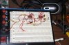
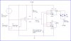
A drawing is attached as well as a picture of the rats nest bread board. Using a single comparator of the 4 in the LM339 I set a reference voltage on pin 5 using a 50K potentiometer. I would have rather used 100K but I had a few 50 K pots available. Keep in mind I used what I had. I also used a 5 Volt supply as it was convenient. This could be done with lower power chips and lower voltage chips. I set my reference voltage on pin 5 of the LM339 at about 2.5 Volts. I then adjusted my pot in series with the photo cell so it wouldn't trigger the comparator with ambient room light.

The output of the LM339 on pin 2 drives a 7474 type D Flip Flop. Normally at power up the RED LED is illuminated. When a flash fires the flip flop does its thing and the GREEN LED lights. I simply used two LEDs for test purposes. For your application you would replace the single RED LED with a transistor to drive your several LEDs. The reset button in the circuit will "ARM" the 7474 and the RED LED will again illuminate.

Notice in the picture of the rats nest the GREEN LED is illuminated. Every time I tried a flash and took a picture the red extinguished and green came on showing only the green being illuminated. Meaning that if there was no green connected the red would be extinguished when the camera actually caught the image.

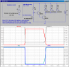
Since flash can vary I tried this with two cameras. I used an older Canon EOS 10D and a new Canon EOS 7D for test purposes. The results were pretty much always the same. I was actually surprised the photocell responded as well as it did.

I am not saying this is an ideal solution but figure it could be a good start. I am sure someone here can design a similar circuit using newer parts. Additionally I figure this could all be done on a single little 8 pin micro controller chip. I didn't take that route as many people don't want to mess with programming a uC chip.

Anyway, hope this helps a little...

<EDIT> I did not show decoupling caps on the chips power pins. I would use .1 uF caps there. I did not show the remaining 3 comparators in the LM339 which would have their inputs tied to ground. Although I wired both D flip Flops in the 7474 I only used the outputs of one of them. Again, this was just a rough draft of a test circuit. :) </EDIT>

Boo, Boo I just noticed in the drawing that Pins 2, 4, 10, and 12 were not tied to 5 Volts and they should be or no workie, workie. My bad.

Ron
 

Attachments

  • Flash Sense..jpg
    Flash Sense..jpg
    112.9 KB · Views: 239
  • Flash Toggle..jpg
    Flash Toggle..jpg
    81.7 KB · Views: 283
Last edited:
Thanks. if it works with your 70D it should works with mine. I will have to experiment a little with the transistor to power le LED as my knowledge is quite limited on this subject.
 
Much will depend on your LEDs. Parameters like forward voltage and current. I don't know what you have so it is difficult to say what you will need. However, if you go with a circuit like what I posted I would probably use a simple 2N2222 for a driver transistor. It's a pretty popular NPN switch. Also for what it's worth since I wired the full 7474 chip you could actually very easily use both available outputs. Each output driving a transistor and each transistor driving maybe 3 LEDs which should give you good illumination for focusing.

Ron
 
I'll through in another option. I haven't bench tested the whole thing. Just a combination of things that have worked for me in the past.

The flash detection circuit, L1/Q1/R1, is from a remote flash slave I built many years ago. Worked great triggering an SCR...triggering a flash unit. The detection circuit triggers a 555 monostable circuit. The output of the 555 is normally low and keeps Q2 turned on, that keeps the LEDs on. Once triggered, the 555 output goes high, turning off Q2 and the LEDs for 0.1 second...then back on. No values on R4/R5/R6/R7/Q2 because as Ron said, we need the info on the LEDs. The photo transistor Q1, FPT100, may not be available now, but could easily be replaced with something like: Jameco Electronics Opto & Illumination: VISHAY INTERTECHNOLOGY, INC. : BPW77NA
ken
 

Attachments

  • 555 Monostable Fl&#9.gif
    555 Monostable Fl&#9.gif
    18.2 KB · Views: 527
Last edited:
Would it not be far easier to hack a remote control (usually cheap enough but **broken link removed**) and then have the first button press (of a standard two stage design) temporarily inhibit the led?

You see the thing that would concern me with sensing the flash is that you are building a circuit to detect the light from the flash that will be used by the camera to expose the picture - I am not sure if the led will be extinguished in time?
 
Here is a much simpler circuit using a CdS PhotoResistor. Should turn off quickly enough. It will be slower turning back on when it doesn't matter.
 

Attachments

  • D12.png
    D12.png
    45.7 KB · Views: 326
Nice suggestion Ken and simple too!

Ron
 
Here is a much simpler circuit using a CdS PhotoResistor. Should turn off quickly enough. It will be slower turning back on when it doesn't matter.

That is slick also. Real simple.

Ron
 
I might be concerned that the "shutter" could be active briefly before, or after, the flash.
 
Status
Not open for further replies.

Latest threads

New Articles From Microcontroller Tips

Back
Top