Continue to Site

Welcome to our site!

Electro Tech is an online community (with over 170,000 members) who enjoy talking about and building electronic circuits, projects and gadgets. To participate you need to register. Registration is free. Click here to register now.

  • Welcome to our site! Electro Tech is an online community (with over 170,000 members) who enjoy talking about and building electronic circuits, projects and gadgets. To participate you need to register. Registration is free. Click here to register now.

LED fade on - hold - fade off circuit

Status
Not open for further replies.

tsdgen

New Member
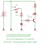
Hi, I plan to make a handheld 6 LED flashlight. I have this idea to 'sophisticate' the switching on and off a bit by making the LEDs fade on for 1 sec when switched on then hold its brightness then fades off for 1 sec when its switched off.

I need help for the simplest circuit to achieve the fade effect. I'll be constructed into a usual sized flashlight.

Im a novice on electronics so please be very instructive especially in mentioning the component values.

Thanks in advance!
 
Hmm well, fading is usually done with PWM (Pulse width modulation - google it). You could control the PWM with a voltage input.

A simple resistor-capacitor combination on the PWM's input would give it a 'soft start'. That is, when you power it up the PWM will start with a low duty cycle (dim LED's) and slowly, depend on the values you use, increase brightness until it the PWM duty cycle is high (or full on) giving you full birghtness.

As for turning off, this gets tricky...as the flash light will still have to be powered when you press the 'off' switch' in order to fade it out.

A very simple idea would be to use a capacitor across the LED's, in parallel with them, although this depends on how you wire up the LED's.

Btw, don't worry about component values for now, they just determine the speicifcs of the circuit. Of course they are important, but you can do the maths to work out the exact values once you have an idea of how you're going to do things.

Blueteeth

Edit: To other people who reply, I intentionally didn't mention 'microcontrollers' as he said he was a novice, so lets not scare him away by talking about setting up a microcontroller development system, which would be over kill anyway.
 
Last edited:
actually, as soon as you mentioned PWM i thought this project isnt that easy after all. I was researching before all this and so far what i have found is a continous fade on and off by 555. i was hoping theres a solution similar as that.
 
A large enough capacitor in parallel to the leds should work. Perhaps add a large bleeder resistor too.
 
Like Externet said ,use a capacitor, there is a formula for the RC time constant that will determine how long it will take for a capacitor to charge or discharge.
 
I wanted to post the exact same thread but fear that Im in a far less knowledgeable boat then the OP. a 555 what? PWM?

Is there a circuit you can buy that does this? I just applied 12v to a 470uF cap parallel with a led with correct resistor attached and it made a sizzle sound before getting hot and dieing. lol

I have a 30cm led lighting strips that pull approx 180mA and I want to make it fade in and out whenever the car door is open or closed..

like this one - click for link pity this guy won't get back to me, otherwise I wouldn't have a problem. Im watching this thread closely, trying to comprehend whats being said but I need noob instructions or something. lol.
 
Capacitors sound like they would do pretty much what you want, although there are a couple of problems when used in this situation:

LED's, like all diodes have a voltage drop across them. That is to say that, for,say a white 'LED' its vdrop would be around 3.2-3.6V (depends on the current going through it). If you apply a voltage less tahn this across it, it will not light. This is because current only flows when the voltage is above this, and of course, no current = no power = no pretty lights. A resistor in series with an LED limits the current. If you apply 5V to the resistor/LED combination, the LED 'drops' its voltage, leaving the voltage across the resistor as 5V - LEDdrop, in this case 5v - 3.6V = 1.2V.

Using the wonderful formula: V=IR, rearranged to find out current we get: I = V/R. Where V is the voltage across the resistor (1.2v in this case) and R as the resistance.
For a resistor of 120ohms, I = V/R = 1.2/120 = 10mA. - pretty reasonable for an LED.

Now, if we place a capacitor across the LED and resistor, when we apply power the capacitor charges up, quite quickly, as we are essentially placing a voltage directly acrosds it with no series resistor. It starts at 0v across the cap...this means the LED will not light. The LED will only begin to light when the voltage across the capacitor is equal or greater than the LED voltage drop. Now it is like applying an increasing voltage across the resistor/LED.

Since the LED's drop is fixed, it is like slowly increasing the voltage across the resistor, from 0 (where the cap voltage is equal to the LED drop) to 1.2V (where the cap is fully charged and is equal to our 5v supply). Looking at the I=V/R...as R is fixed, increasing the voltage across the resistor, increases the current allowed to flow through it. - Its the current flwing through the LED which determines its brightness, and since the resistor and LED are in series, this current is the same for both.

So, when you turn on your flashlight, the LED won't light until the cap reaches the LED voltage drop. And then it will quickly go to full brightness. The only way to control how long it takes from being 'off' to 'fully on' would be the value of the capacitor used. Without yet another series resistor, the capacitor will undoubtedly charge very quickly...a lot less than a second.

The second problem, which may or may not be a problem, is down to how the capacitor voltage increases. When applying a constant voltage across a capacitor, its voltage rises non-linearly. That is to say, it doesn't 'ramp', it's voltage rises very quickly at first, then its increase gets slower and slower. google 'RC time constant' to see the charge curve.

Because as I mentioned before the LED will NOT light, until the cap voltage is equal to the LED voltage drop, this initial 'quick voltage rise' has no affect on our LED, so once the LED begins to light, the voltage rise on the cap is actually quite slow....so this 'may' be an advantage in this situation...since we do not want it to get from 'off' to 'on' within some stupidly small time-frame, like 3ms :)

Now, if we were to put the capacitor in parallel with the LED (not as before where we put it in parallel with the LED AND resistor) the same prinnciple applies. Except....this time the capacitor charges through the series resistor...limiting the current available to the cap...causing its voltage to rise much slower. However, this idea brings its own issues....if the caps voltage rises above the LED's forward voltage (voltage drop) then excessive current can flow from the cap, to the LED...causing it to meet its maker.

Bradass: I suspect the reason it 'sizzled' was because of the capacitors voltage rating...OR the series resistor being of incorrect value, perhaps even incorrect polarity of the capacitor used. Always pick a capacitor with a votlage rating much higher than your power supply is capable of providing. So, for a 12V supply, a capacitor with a voltage rating of 16V is the minimum, probably 25V just to be safe.


Sorry for along and detailed post..but, if you knew all this already, then it is I who have wasted their time...but I was hoping it would give you a basic understanding of whats going on :) If you wish to know more, I'll psot some example schematics along with graphs and wonderfully boring maths.

Blueteeth
 
The capacitor sizzled because its polarity was connected backwards. You are lucky it didn't explode and injure you.
 
Since I have nothign better to do (day off work right here lol) I thought about the simplest way of doing this....whilst being a good bit of education for those who are complete novices.

It's a simple circuit that uses a transistor, it DOES require a dual toggle switch...which your flashlight may not have, but it does exactly what you require, and allows you to determine how quickly it fades in, and fades out when you turn it on/off. Its just a question of part values. Great introduction to basic analogue electronics...you can tinker with part values to see what each part does and its affect on the LED.

Probably overkill, but hopefully it can be of some use to you guys, especially if you can learn something new.
 

Attachments

  • LED_soft1.png
    LED_soft1.png
    6.5 KB · Views: 2,289
Like Externet said ,use a capacitor, there is a formula for the RC time constant that will determine how long it will take for a capacitor to charge or discharge.

The problem with attempting to use RC constant to gradually fade a LED is that RC constant is more involved with the time required to reach a particular voltage, rather than with gradually reducing or increasing voltage.

For instance, a 1Meg resister and 2.2 uF cap would, by formula, produce an approximate 2.2 second delay in either charging or discharging the cap. However, when the LED turns on or off during this charge or discharge depends on when there is sufficient voltage to turn on the LED, or insuffiecent voltage to sustain the LED's operation.

RC constant, very simply, is the time it takes the cap to charge to 2/3 applied voltage, or to discharge to roughtly 1/3 the voltage it was charged to. During this fluctuation, the voltage point at which the LED turns on or off is reached of a sudden, not gradually.
 
blueteeth:

it was lengthy but very informative. i wont mind learning those as long as it could be a step in making an idea into reality. and i got the concept...well, pretty much of it. :D

thanks for the diagram, i can tinker with it for a start.

schematics and graphs are welcome. do scrimp on the math though! haha!

thanks, you guys.
 
Last edited:
Status
Not open for further replies.

Latest threads

New Articles From Microcontroller Tips

Back
Top