BobInnabagg
New Member
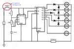
Here's the scenario. Total 6 LEDs. When power is applied the first LED turns on, then turns on second LED while first LED remains on. Then the third LED while the first two remain on, and so on up through the 5th LED. Then those 5 LEDs turn off and the 6th LED turns on and fades off. I thought about using the 555 timer with a 4017 setup and just tying each LED plus the previous one to the next output of the 4017. I.E., the first 1 would turn and go out then the next output stage would turn on 2 LEDs, then 3 and so on through the 5th one. This is basically a charger light setup whereas, as it ramps up the next light will illuminate, but there is no charging. It's all for show. The 6th LED is a burst, then fades, then it shuts off, no repeat until switch is pressed again and the cycle repeats. Not sure if this will work, and how do I shut it off? Or, Is there a better way, using discrete components?
 - but I presume you've only done it for fun, rather than a practical use?. Particularly as it's easily duplicated with a simple row of LED's
