Continue to Site

Welcome to our site!

Electro Tech is an online community (with over 170,000 members) who enjoy talking about and building electronic circuits, projects and gadgets. To participate you need to register. Registration is free. Click here to register now.

  • Welcome to our site! Electro Tech is an online community (with over 170,000 members) who enjoy talking about and building electronic circuits, projects and gadgets. To participate you need to register. Registration is free. Click here to register now.

L T spice

Status
Not open for further replies.

MrDEB

Well-Known Member
I decided to give this software a try again.
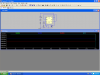
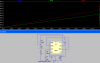
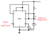
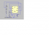
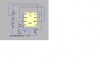
have a simple 555 connected as a triangle wave output.
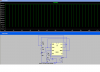
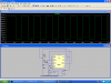
hit simulate and move the red probe over pin 3 but get no wave.
must be doing something wrong.
is there a website that has a tutorial or ??
this looks better than multisim. not as easy as Tina but Tina has limited components
any help??
 

Attachments

  • 555 screen shot.PNG
    555 screen shot.PNG
    58.9 KB · Views: 488
The discharge pin is misconnected. Connect it to the junction of R1 and R3; not to +6V!
 
I think you also need to have a ground pin at the negative ternimal of the battery.
 
getting somewhere but ??

added the ground and changed the dis pin (that was a really dumb moves on my part) and now getting a partial triangle wave.
possable to get the full wave?
this is just a learning experience so if I need tochange componets??
after this going for a square wave.
in the samples they show a square wave but I can't get the scree to do same??
pretty sure this it a simple problem with a simple solution
LT spice newbi
 

Attachments

  • 555 scr shot.PNG
    555 scr shot.PNG
    25.7 KB · Views: 379
Why don't you look at the datasheet of a 555 to see that yours is connected completely wrong?
The Trigger and Threshold pins must be connected to the timing capacitor.

If the resistors are the correct ratio then the pin 3 output is almost a square-wave.
The timing capacitor has a curved waveform similar to a triangle wave and is a high impedance.
 

Attachments

  • 555 oscillator3.PNG
    555 oscillator3.PNG
    9.9 KB · Views: 462
schematic as per Forest Mimms

page 99 first edition first printing 1982 engineers notebook 2
of coarse the schematic could be wrong?? or I drew it wrong??
 
R3 is supposed to be a pot

but how to use in spice? so I just change the value
still no wave
here is schematic w/ corrections
are then changes I need to make to preferences?? in order to "see" the full triangle wave.
 

Attachments

  • 555 timer.PNG
    555 timer.PNG
    19.7 KB · Views: 492
but how to use in spice? so I just change the value
still no wave
here is schematic w/ corrections
are then changes I need to make to preferences?? in order to "see" the full triangle wave.

Look at my sim. Note that V(CV)=8V, which is 2/3 of Vdd (12V). V(RC) switches at 1/3Vdd (4V) and 2/3Vdd (8V), and the asymmetry in the output. The timing cap charges toward 2/3Vdd (8V) through two resistors in series (R1 + R2), but it discharges to 1/3Vdd (4V) only through R1...

Note the use of .IC statement to model the correct start-up behavior.
 

Attachments

  • 555test.gif
    555test.gif
    79.2 KB · Views: 354
Last edited:
still no wave
here is schematic w/ corrections.
You still did not connect the Trigger pin and the Threshold pin to the timing capacitor C1.

Since your timing capacitors are backwards then the capacitor charges very slowly through both then discharges very quickly through the wrong one. Then the triangle wave will be a sawtooth wave.
 
Last edited:
well trying again??

supposed to be a square wave but it sure isn't what I was hopeing.
MikeMi mentions .IC statement
what and where to ???
note this LT spice is it the same as switcher cad
Videos at CMOSedu.com
 

Attachments

  • 555 timer2.PNG
    555 timer2.PNG
    33 KB · Views: 326
Your problem is you made R1 = 1m, which mean 1 milliohm. I think you want 1MEG for 1 Megohm. Right click the resistor and type 1MEG for the resistance value.
 
Last edited:
houston we have blastoff

changed to 1 meg and expanded to 120s
now to add transistor cap circuit
see post tiny schematic
 

Attachments

  • 555timer3.PNG
    555timer3.PNG
    73.5 KB · Views: 225
Status
Not open for further replies.

Latest threads

New Articles From Microcontroller Tips

Back
Top