Continue to Site

Welcome to our site!

Electro Tech is an online community (with over 170,000 members) who enjoy talking about and building electronic circuits, projects and gadgets. To participate you need to register. Registration is free. Click here to register now.

  • Welcome to our site! Electro Tech is an online community (with over 170,000 members) who enjoy talking about and building electronic circuits, projects and gadgets. To participate you need to register. Registration is free. Click here to register now.

L T spice

Status
Not open for further replies.
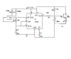
The only problem you have now is the ratio of R1 and R3. I see you made it huge to get an approximation to a square wave. That only works because your frequency is so low, and you can make those resistors high. But if you want to scale to a higher frequency, R3 will become too small. A better way to make a square wave is to make those resistors the same value, and use a diode across R1 anode connect to the junction of R1 and R3. That allows the cap to be charged thru R3 only, and discharged thru R1.
 
going to sim this circuit

want to get a slow fade from full on to off
 

Attachments

  • 555 dimmer.PNG
    555 dimmer.PNG
    26.1 KB · Views: 202
now what??

I took measurments three different points
emitter/D1
D1 current probe
D1/R2
if reading (got to be a better way than estimating) but led is on for 4 seconds?
off ??
 

Attachments

  • dimmer screen shot.PNG
    dimmer screen shot.PNG
    72.2 KB · Views: 149
changed things around a little

now the LED comes on slowly, on for 2 seconds then off I think? if reading the scope correctly??
tried different caps etc.
would like it to turn off slowly as well??
this LT spice is pretty good
 

Attachments

  • dimmer3.PNG
    dimmer3.PNG
    71.6 KB · Views: 157
A "real" LED will appear to be constantly on. That's because R3 will keep the output high for 300 times more than R1 will keep it off. See post #21 for how to make the output 50% on and 50% off.
 
Didn't you hear me?
You have the timing resistors R1 and R3 backwards so the timing capacitor C1 charges slowly then discharges very quickly. Then the output of the 555 is high most of the time.

If you swap the positions of R1 and R3 then the timing capacitor will charge and discharge in almost the same amount of time and the LED will slowly get brighter then slowly get dimmer.
 
I tried that

I may have gottne sidtracked inserting a diode across the second resistor and making both the same.
ill sim again
 
You don't need a diode if the timing capacitor charges with 310k then discharges with 300k. Then the output is 51.7:48.3 duty cycle.
 
Never claimed that he needed a diode. But it's a good way to get 50/50 and it scales better when changing resistor values.
 
triggering a monostable in LT spice

well were getting somewhere I think.
Now how to trigger a monostable 555?
looked at the independent voltage source as it has a pulse output but ??
basically want to input a low into pin 2 of a 555 to trigger a monostable .
must be a simple solution.
I wish the help files were expanded further or a help file on some of the components such as the voltage controlled switch or independent voltage source.
 
well were getting somewhere I think.
Now how to trigger a monostable 555?
You have to understand the 555 before you try to ask LTSpice:D

looked at the independent voltage source as it has a pulse output but ??
basically want to input a low into pin 2 of a 555 to trigger a monostable .
must be a simple solution.

Could it be simpler than this: Since it takes a momentary low on pin 2, use a voltage source as I show below. Note the inverted signal...


I wish the help files were expanded further or a help file on some of the components such as the voltage controlled switch or independent voltage source.

Its all there, you just have to look a little deeper....
 

Attachments

  • 555test.gif
    555test.gif
    73.3 KB · Views: 178
here is what I get

with using LOAD1 componet
the monostable is supposed to be 3 seconds long.
 

Attachments

  • mono scr1.PNG
    mono scr1.PNG
    29.7 KB · Views: 137
What is the "load" device supposed to represent???? If you want to trigger a 555 such that it goes through one timing cycle each time an external trigger is applied to it, then apply a low going pulse (which is shorter than the 555's timing period) to pin 2.
 
in the load componet

it has the same parmeters as the voltage source (appears to)
ran using the voltage source as per your post and waveform looks the same??
 
it has the same parmeters as the voltage source (appears to)
ran using the voltage source as per your post and waveform looks the same??

Ok, what confused me was the pullup resistor and the way it was drawn. Note that my voltage source was "inverted" (starts high, and goes low to trigger the 555, and then back high again. You can play with the timing network to get any width you want, as long as 5K < R < ~5meg.
 
in your post showing waveforms

what is the blue wave going at a 45 degree angle?
on your schematic you have RC on pin 6 ??
reversed voltage source??
 
on to another schematic?

why when I simulate this circuit - two LEDs connected to 555 output, the LED to ground shows current flow but the LED connected to Vcc to pin 3 output shows no current.
why doesn't it show current when the 555 output goes low?
maybe a reference to ground?? issue.
 

Attachments

  • 555leds.PNG
    555leds.PNG
    34.7 KB · Views: 144
Status
Not open for further replies.

Latest threads

New Articles From Microcontroller Tips

Back
Top