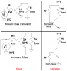
I am making very simple inverter for small load like CFL, I have also used common emitter but it was not boosting current and pls tell is there is any difference in gain of transistor when operating in forward-forward bias and reverse-reverse bias.
as, i was using reverse-reverse biased in darlington it was not working pls tell...!