Electro Tech is an online community (with over 170,000 members) who enjoy talking about and building electronic circuits, projects and gadgets. To participate you need to register. Registration is free. Click here to register now.
Welcome to our site! Electro Tech is an online community (with over 170,000 members) who enjoy talking about and building electronic circuits, projects and gadgets. To participate you need to register. Registration is free. Click here to register now.
New lead acid batteries are rated for CCA which is for cold temps with (?) a 4.5V drop. Thus 4.5V/450 A = 10 mohm is a reasonable value to choose with an aged battery at room temp. But your alternator won't be able to sustain this current beyond the rated 30 s test time. But it will realize some losses.
1 mohm might be possible if the battery can supply 4500 A for 30 sec. (Not)
When performing simulations of complex circuits like yours, something that has helped me TREMENDOUSLY is to follow the divide-and-conquer approach.
Meaning that you should simulate a stage and ensuring that it works correctly before proceeding to the next stage.
So! Please make sure firstly that the astable circuit oscillates properly and at the correct frequency.
To do so, make a copy the .asc file and rename it something like experiment1. Erase everything but the battery and the astable. Troubleshoot it…in case it doesn’t start up, usually you have to set some initial conditions to simulate the natural unbalance that occurs on a real world circuit.
After it works, proceed to the next stage and so on.
The 2N6277's are good at dissipating heat, but this makes the source impedance much higher than if you used a power FET half-bridge. For transistors in saturation and diodes a rule of thumb is that the incremental resistance can be derived from the datasheet plots for each device, but these cannot compare with 1 mohm FETs.
If you have a ~2kW load ~ 120V * 16A or 7.5 Ohms with a 1:10 turns ratio n=0.1 the load referred to source Zs= 7.5* n²= 7.5 * 0.01 = 75 mohms.
Each NPN is in this ohmic range only if Ib/Ic=10. The emitter resistors are necessary to prevent thermal runaway when the transistors are mismatched. Thus matching them requires they all be thermally bonded to track Vbe vs temp and my rule of thumb is to choose 50 to 100% of the nominal Re= 40 mohms when driven to these currents. I suspect the base drive is inadequate and that you need one 2N6277 to drive 10 of the same.
The temperature rise will also tell you immediately where your losses are.
Since the base drive drops in voltage and these are all emitter followers you need to boost the base voltage. FETs do not have this problem and complementary or dual Nch half-bridges with bootstrap boost voltage for the high side are preferred.
Bottom line, this design is inadequate to drive 2kW out. The source would need to be 14.2V to get 120V out at low loads.
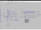
You are running the transistors in a darlington arrangement which will lead to the final transistors not being saturated.
The collectors of Q7 and Q13 should be supplied by resistors from the +ve rail. That has already been done with the collectors of Q5 and Q6.
In the arrangement shown in post #1, when the Q8 - Q12 turn on, the collector voltage will fall, and that is what feeds Q7 collector as well, which in turn feeds the bases of Q8 - Q12. You will not be able to get the collector voltage below about 0.8 V.
Unfortunately it's still a completely crappy circuit, square wave only, not even any 'dead band', and if it works at all will very likely soon self-destruct.
The entire design is crap - similar ones are all over the Internet, and none of them work.
What EXACTLY are you trying to do?, and what are you trying to power.
There are low cost 'proper' inverts available, which work properly, with many giving pure sine-waves or (so called) 'modified' sine waves. Square waves, like the attempt in this thread are mostly useless, even if they work at all.
Yes, I was looking online. For 60 bucks I could get what I want, but there's a satisfaction in building your own.
I cheated last night and measured the Primary on a transfo I have and got my design with parallel transistors working a lot better, but has you say it's junk. I am looking around now looking for a 2KW MOT primary to measure and see how that works out, just to satisfy my curiosity.
This site uses cookies to help personalise content, tailor your experience and to keep you logged in if you register.
By continuing to use this site, you are consenting to our use of cookies.