Continue to Site

Welcome to our site!

Electro Tech is an online community (with over 170,000 members) who enjoy talking about and building electronic circuits, projects and gadgets. To participate you need to register. Registration is free. Click here to register now.

  • Welcome to our site! Electro Tech is an online community (with over 170,000 members) who enjoy talking about and building electronic circuits, projects and gadgets. To participate you need to register. Registration is free. Click here to register now.

Sinusoidal mains inverter is a cinch?

Status
Not open for further replies.

Flyback

Well-Known Member
Hi,
Why is the sinusoidal mains inverter said to be so difficult to design?

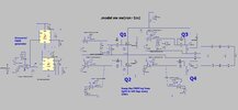
The attached LTspice does it no problem..
There is no need even to adjust the amplitude of the reference sine wave.
If you change the load on the output, it automatically changes the sinusoidal current to suit it...and puts the same sine voltage across it.
All open loop!
Why is this said to be so difficult?
(Not Grid_tied here, of course)

Generating the ref sine signal....i'd say this is best done by a mini LLC converter, wouldnt you agree?....tap off the sine with a current transformer, and use that as the ref sine? Big L and C values for 50Hz sine, but low current. AYK, its a train of half-sines thats actually needed (rectified sine)

As you know, when the load is purely a resistor of constant value, then the simple inverter principle above applies, but when there is rapid load changing , or non linear loads, then we need a control algorithm to be added.

Though the below appears to be the only chipset available to do this quickly. Do you know of any others?
https://www.ti.com/lit/ug/tiduay6e/...185&ref_url=https%3A%2F%2Fwww.edaboard.com%2F
 

Attachments

  • Inverter_2_a.asc
    15.9 KB · Views: 146
  • mains inverter.jpg
    mains inverter.jpg
    174.4 KB · Views: 161
Last edited:
Why is the sinusoidal mains inverter said to be so difficult to design?
Who says it is? It's certainly more expensive to manufacture than a bog-standard so-called 'modified sine-wave' type.
Btw, Windows Defender reports a security issue with your asc file.
 
Yes i think .asc files do that
I've not noticed it with other asc files. I wonder if a recent Win update has changed the situation?
 
Thanks, overload protection would do with a hall sensor chip in the bridge. AC input type.
Would just turn off if overload current seen..
Comparator at output of hall sensor.
Then cust would have to power cycle to get it back on. (hopefully theyd remove the overload)
 
Last edited:
overload protection would do with a hall sensor chip int he bridge. AC input type.
Yep, that's the easy bit.
Plus inrush control if it's anything other than trivial power rating.

What about the ten (at least) "cheat" voltage sources you are using to create control signals?

Try adding all those in full, then see if you still think it's simple!
 
Thanks
Generating the ref sine signal....i'd say this is best done by a mini LLC converter, wouldnt you agree?....tap off the sine with a current transformer, and use that as the ref sine? Big L and C values for 50Hz sine, but low current. AYK, its a train of half-sines thats actually needed (rectified sine)
 
Don't most commercial devices generate the sine using a look-up table?
 
Don't most commercial devices generate the sine using a look-up table?
I would have expected it to be generated digitally.

A look-up table with linear interpolation would only need fewer than 10 points for a quarter cycle to be far more accurate than a typical mains sinewave.

Even fewer points are needed if a lookup table is used for 0 - 45°, and then for 45 - 90 ° the sine is taken as the square root of (1 - sin(90 - angle)^2). With just two points, for 0 and 45°, the maximum error of the sine wave is less than 3%.

I did something similar to work out the arctangent. I used a look-up table of 8 points with linear interpolation. for 0 - 45°. For values over 1, I took the inverse and used 90° - (lookup result). The result was within 1° of the correct answer.
 
Last edited:
thanks, only other (analog) way to make a 50Hz sine i can see at the moment is to rc filter a 50Hz square wave, and then amplify it back up? Plus ideal diode rectification because we only want a train of positive haversines....of about 1V peak.
 
only other (analog) way to make a 50Hz sine i can see at the moment is to rc filter a 50Hz square wave
How about this analogue approach? :
1672679713042.png

THD is only 1.4% in the sim.
 
What about the ten (at least) "cheat" voltage sources you are using to create control signals?
Thanks, the sim of it is now flashed out to more real circuitry, but it takes ages to run....
 

Attachments

  • 50hzINVERTER_jan3_SINE CHEAT.asc
    35.8 KB · Views: 139
Status
Not open for further replies.

Latest threads

New Articles From Microcontroller Tips

Back
Top