Electro Tech is an online community (with over 170,000 members) who enjoy talking about and building electronic circuits, projects and gadgets. To participate you need to register. Registration is free. Click here to register now.
Welcome to our site! Electro Tech is an online community (with over 170,000 members) who enjoy talking about and building electronic circuits, projects and gadgets. To participate you need to register. Registration is free. Click here to register now.
Most intercom calls are dialed then at the end of a call are disconnected.
You don't want the system left turned on so that a person outside at the slave can hear everything at the master and you don't want the master to hear all the noise outside at the slave.
Have a doorbell. When the person inside at the master hears the doorbell then the intercom power is turned on for the call and turned off when the call is finished.
yaya, i want intercom at the end of a call are disconnected, person outside at the slave cannot hear everything at the master.....
if i want to have a doorbell , how can i connect doorbell togather with the intercom ? doorbeel output is connected to the "master" or "slave"... and after end of communicating , how i can stop both intercom , so i need to addition a switch off button?
I guess it won't be difficult to recognize the difference between "SW1" and "S1" as well as "Q1" and "T1".
Since Eagle would connect circuits with the same net names different names were used, e.g. "AF-A1" and "AF-A2", both connected at the junction of the transistor collectors (T1) and C3 and T1A and C3A respectively.
The shielded cable connects exactly at the same connection points with the difference, that a three wire shielded cable is used connecting the power supply from the master board to the slave board.
When using a single wire shielded cable connect that to pins2 and 3 of the connector with pin2 being the "hot wire" (labeled "AUDIO" on the PCB design) and pin3 being the shield (labeled "SHIELD").
Use an unshielded two wire cable to connect pins1 (+12V) and pins4 (circuit ground) between boards.
I tested the clarity of the board layout asking my 12 year old stepdaughter where she would connect both boards and her answer was: "just 1:1 as labeled".
One two wire unshielded cable to connect the 12V power source to the solder pads on the master PCB. Those solder pads are only present on the master PCB and they are located halfway between connector Y1 and C7. They are labeled "+12V" and "GND".
The second cable should be a four wire shielded cable (If you can get 3 wire shielded cable it will suffice as well.)
I redrew the wiring since I don't like thick lines crossing parts and text in a schematic layout.
Additionally to the wires connecting pins I added a small sketch showing the pins labeled MA1 through MA4 and SL1 through SL4 which stand for master and slave.
Using a four wire cable it won't hurt if you connect the fourth wire to the shield.
If that drawing doesn't help you now I'm afraid nobody can help you.
There are hundreds of low power amplifier ICs available. Use a TDA2822M or LM386 instead.
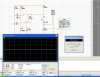
Why simulate a simple audio amplifier when all its spec's are in its datasheet?
Your Multisim schematic shows a transistor with no input signal and its base is disconnected from its base bias resistors. So of course there is no output.
This site uses cookies to help personalise content, tailor your experience and to keep you logged in if you register.
By continuing to use this site, you are consenting to our use of cookies.

")