Solderspitter
New Member
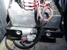
I would like to build an electric power door controller to replace the obsolete commercial device in a project RV.
I did something wrong cutting out old wires and now the old one doesn't like me. I cannot find a manual for this thing, so would be better and far less costly to have something I can service myself from hobby parts.
I had this one rigged with an aftermarket remote fob, perhaps I could integrate one in a new circuit?
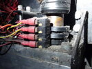
My guess is that it's a pwm stepper driver. The motors look like screen wiper arm type, 12v. Not sure about power rating, by the gauge wire, 10Amp or less. Two doors, a motor on each.
There must be a way to use Arduino or some kind of pre-made boards to put something together?
Press button, circuit activates, doors open. Press button again, circuit activates, doors close.
The original was connected so that the doors would always close before you could drive the bus. Bit of a nuisance.
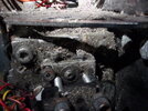
It looks like a simple circuit with micro switches running on contacting cams to detect the limit of travel.
The doors lift up a little when closing, I guess that's why there's one switch that's not on one cam.
Can I get some suggestions for parts to figure out a circuit?
I did something wrong cutting out old wires and now the old one doesn't like me. I cannot find a manual for this thing, so would be better and far less costly to have something I can service myself from hobby parts.
I had this one rigged with an aftermarket remote fob, perhaps I could integrate one in a new circuit?
My guess is that it's a pwm stepper driver. The motors look like screen wiper arm type, 12v. Not sure about power rating, by the gauge wire, 10Amp or less. Two doors, a motor on each.
There must be a way to use Arduino or some kind of pre-made boards to put something together?
Press button, circuit activates, doors open. Press button again, circuit activates, doors close.
The original was connected so that the doors would always close before you could drive the bus. Bit of a nuisance.
It looks like a simple circuit with micro switches running on contacting cams to detect the limit of travel.
The doors lift up a little when closing, I guess that's why there's one switch that's not on one cam.
Can I get some suggestions for parts to figure out a circuit?