Continue to Site

Welcome to our site!

Electro Tech is an online community (with over 170,000 members) who enjoy talking about and building electronic circuits, projects and gadgets. To participate you need to register. Registration is free. Click here to register now.

  • Welcome to our site! Electro Tech is an online community (with over 170,000 members) who enjoy talking about and building electronic circuits, projects and gadgets. To participate you need to register. Registration is free. Click here to register now.

Help Increasing Time Delay on Motion Sensing Camera

Status
Not open for further replies.

Al Chemist

New Member
I wonder if I can pick your brains with help on adjusting the amount of time a Motion Activated Digital Video Recorder records when it receives a signal from a motion sensing camera that it is sensing movement.

Currently it stops recording the moment it ceases to sense movement, I would like it to carry on recording for maybe 10 seconds. but adjustable up to 60 seconds, maybe more, would be even better. :)

First of all the unit is a Angel Eye JS309M Mini Digital Video Recorder and the camera is a JS619 Motion Activation Camera.
**broken link removed**

Unusually the camera sends a signal to the mini DVR when it senses movement. (usually this a function of the DVR and not the camera)


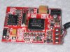
the camera connects to the DVR via a 4ring 2.5mm Jack,

The 4 connections are
VO = Video Out
Ground
5v (Measured 3.7v same as the DVR battery)
MO = Motion signal (Measured constant 2.99V which dropped to 0V on seeing movement)

I wasn't expecting that last measurement, I was expecting the camera to send a voltage pulse when it saw movement, but there is a logic to dropping the signal to zero on movement, it means if you plug any other camera into the AV-in socket the unit will automatically record as there will be no motion signal.

Last thing is, I'm still learning to solder without burning everything within a 30m diameter :eek:, so the fewer components I need to solder the better!! :eek:

Your help in this matter is greatly appreciated, thanks in advance.
Al

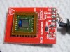
Photos of the camera PCB attached, and the user manual for the DVR and camera.
 

Attachments

  • JS308&JS309M User Manual.pdf
    674.6 KB · Views: 1,708
  • JS619_pcb01s.JPG
    JS619_pcb01s.JPG
    246.2 KB · Views: 630
  • JS619_pcb02s.JPG
    JS619_pcb02s.JPG
    347.2 KB · Views: 608
I would imagine it's a function of the software?.

No there's no way to adjust the time on the DVR or the camera, it's either on or off.

Normally with CCTV you have software in the DVR that takes care of the motion sensing, but this unit senses from the camera hence the MO contact in the camera back to the DVR.
 
Perhaps I should clarify, what I'm looking to build is a circuit that takes the constant 2.99V MO input from the camera, and passes it to the DVR.

When it sees 0V on that input, keep the output to the DVR at 0V for say 10 seconds regardless of the input.

Then reset to passing the input to the DVR, if zero volts then maintain that for another 10 seconds.

I hope that makes sense.

I haven't a clue what components that will need so any help appreciated.
 
Cool, thanks Nick.

Plz excuse my ignorance Nick, but is there one of those sample circuit diagrams that is best suited to my application than the others?

I thought it best to ask someone with knowledge of these things, as I do tend to blow things up!! :eek:

Thanks

I was thinking Fig 10a "Missing Pulse Detector"
 
Last edited:
Which 555?

I'll think out loud.. feel free to add comments..

At Maplins they appear to have three 555 variations which may suit my needs.. **broken link removed**


NE555N Timer
ICM7555IPA Low Power Timer
TS555/6CN Low Power Timer

I think I can discount the NE555N Timer as the trigger voltage is 5V I think, and I only have 3v. Also the ICM7555IPA Low Power Timer is called a BiPolar timer, I'm not sure what that is but the circuit diagrams are not what I expected so I'll discount that one.

Leaving the TS555/6CN Low Power Timer as the one to choose. Especially as my input voltage is 3.7v and my trigger voltage is under 3v to 0v.

Is that a good choice?
 
Last edited:
Leaving the TS555/6CN Low Power Timer as the one to choose. Especially as my input voltage is 3.7v and my trigger voltage is under 3v to 0v.

Is that a good choice?

hi,
I would go for the TS555 low power version.:)

As Nigel points out, you need the Monostable circuit from the datasheet.

Also if you want to pull the MO line low [0v] then release to whatever the MO level is, you will also need a general purpose npn transistor, connected as an open collector output

EDIT:
as you have limited electronics experience, I would suggest a DIL 555, not a surface mount device.
 
Last edited:
hi,
you will also need a general purpose npn transistor, connected as an open collector output

EDIT:
as you have limited electronics experience, I would suggest a DIL 555, not a surface mount device.

DIL 555.. do you mean one of these sockets? **broken link removed**

Excellent suggestion. Thanks. :)

I was looking at the transistor in figure 10a and couldn't get a match, so that was going to be my next question after I sorted the 555, which transistor?

It's got to take a 3v signal, of the 7 at Maplins **broken link removed**

4 are low power, 1 is High Frequency, 1 is High Voltage and 1 is Bi-polar.

I'm guessing one of these low power is the way.. **broken link removed** but I haven't done any calculations yet so I don't know which one yet.


All comments welcomed :)
 
hi,

Low power npn will be ok.

I guess the next is a circuit diagram, do you want to post a sketch.?

Use the data sheet for a ref, we will then guide you thru the design.:)
 
I guess the next is a circuit diagram, do you want to post a sketch.?

Use the data sheet for a ref, we will then guide you thru the design.:)

I think this right, sorry I've got no CAD, so old skool pen and paper will have to do ;)

JS619_Dia01.JPG

It highlights a few points,

Looking at the fig 10a circuit diagram (

I'm also not sure which type of capacitor, but the info from Maplins on the T555 says "Choose high values for timing resistors to keep supply currents low and low values for capacitance, which should be low leakage types, not ceramic."

So by high values I assume it's 1MΩ or higher for R

which using the formula Time (seconds) = 1.1 x R x C gives 100µF for C to give T = 11 seconds, where R= 1 MΩ (provided I've put all the zeros in the right place for the calculation ;) )


100µF isn't an incredibly low value for C so I'm wondering if that's OK?
Next question will be which capacitor do you recommend? (It needs to be non-ceramic)


Onto the resistor, I'm thinking of putting a potentiometer in place of R, possibly up to 5MΩ which should give 55 seconds at the top end, but I'm slightly concerned that if it's wound down too low RΩ will be too low and that may have a bad effect on the capacitor. I don't know if it will or if there is a way to limit the lower resistance?


Lastly and a somewhat different subject, when I plugged a USB supply into the DVR, it would record on motion sensing, but eratically, and I presumed that was some kind of back feed getting onto the 0V signal. Do you think putting a diode on the output signal might help this? and would it do any harm to try this?

Next question will be which diode do you recommend ;)


Thanks for your help, I would not have got this far without your input.
 
How does this look?

I'll think out a loud again, just to progress things.

First of all I've updated the circuit sketch to include some changes I 've included..

JS619_Dia02.JPG

Secondly I need to correct my earlier calculations, I did get it wrong (by a factor of 10) so I'll show the calculations, to make it easier to spot any errors there.

I've added a potentiometer, to provide a means of adjusting the time delay, and at the same added a resistor in series with the potentiometer, to prevent a 0Ω reading, (I think the lowest is resistance 2Ω, but it will still drain the battery fast I expect)

New calculations using Time (seconds) = 1.1 x R x C look like this...

The resistors separately
1.1 x 39KΩ x 47µF = 2.0163sec
1.1 x 39000 x 0.000047 = 2.0163sec
+
1.1 x 5MΩ x 47µF = 258.5sec
1.1 x 5000000 x 0.000047 = 258.5sec

= 258.5 + 2.0163 = 260.5163 sec

OR together

1.1 x (39KΩ + 5MΩ) x 47µF = sec
1.1 x (39000 + 5000000) x 0.000047 = sec
1.1 x 5039000 x 0.000047 = 260.5163sec

Gives the same result, delay range now being approx 2 seconds to 4 minutes 20 secs.

I've tried to fill the gaps in my knowledge with "uneducated guesses", I'm particularly concerned about which transistor to select.. I've taken a real flyer by selecting the one I have, also I'm not sure if the Diode I've selected is correct. I've added the diode to try and prevent a backfeed corrupting the MO (motion sensor) signal when I supply the unit from the USB. (I guess you can tell this unit was fairly cheap!! :rolleyes: ) I'm not sure if it will work, but I'm more concerned about whether or not the addition of the diode will effect the timer output.

I have put together a parts list which may do the job without exploding, I'm not sure !! :eek:


Resistor: 2W Res 39K D39K £0.21 **broken link removed**
Potentiometer: Hor Encl Preset 5M N46BR £0.34 **broken link removed**
Capacitor: Minelect 47uF 16V VH11M £0.12 **broken link removed**
Timer: TS555/6CN Low Power Timer RA76H £0.75 **broken link removed**
Timer Socket: DIL Socket 8-Pin BL17T £0.20 **broken link removed**
Transistor: BC558/B 30Vceo,-100mA,500mW,220/475 min/max, 100Hz, QQ17T £0.26 **broken link removed**
2.5MM JACK SOCKET: 4Pole - MJ-068H £1.43 per 2 2.5MM JACK SOCKET, 4P - MJ-068H
2.5MM JACK PLUG: 4Pole, METAL - PSG02797 - PRO SIGNAL £0.77 2.5MM JACK PLUG, 4P, METAL - PSG02797 - PRO SIGNAL
Diode: 1A Schottky Barrier Rectifiers 1N5817 JA46A £0.22 **broken link removed**
PCB:
Box:

Any comments welcomed, I really am working in the dark without a few comments to go on.

Thanks in advance for looking.
 
You don't need a missing pulse detector. Look at the turtorial in the section "Monostable Mode", a little over 1/3 the way into the document. See figure 9a. That's all you need. No transistor is required.
 
Thanks for the response, but are you sure BrownOut?

Perhaps I'm missing something, but I need zero volts to be maintained on the output once zero volts is detected on the trigger cable. I can see that scenario working with the "missing pulse detector" (fig 10a), but surely the Output from the timer will be a voltage of some kind in fig 9a?


If does work without the transistor that will be great, so I hope your right :)
 
All you need is a timer configured in a monostable multibrator, aka "One-Shot." When you get the low pluse from the motion detector, that will trigger the timer. When triggered, the output will go "high" for a time period determined by a resistor and capacitor connected to the timer. That's the delay you will set.

The missing pulse detector won't work for your requirement. I won't go into all the reasons, but it's simply the wrong function.

Unfortunately, the 555 does not have an "active low" signal, so you'll need to connect an invertor between the timer and your recorder to get the "active low" signal you need. You can use an integrated inverter chip, such as this hex inverter as an example. Or you can create a simple transistor inverter. Either way, it's real simple.
 
Last edited:
Here is an example of a simple transistor inverter. The voltage source on the left represents the output of your timer. When the source is 5v, the output of the inverter is 0v, and visa-versa. The transistor can be a common 2N3904, 2N2222 or equivalent.
 

Attachments

  • SimpleInverter.JPG
    SimpleInverter.JPG
    111.7 KB · Views: 435
Last edited:
Thanks BrownOut, I kinda figured there would be some "inverting" of the output involved there.

I'll read all of the info, get back to the drawing board, and try a new circuit sketch. The diagrams for hex inverter totally lost me, so hopefully those transistors will make more sense.

Thanks again, I'll get there eventually ;)
 
Circuit Sketch No3

All I've done here is removed the old transistor setup and inserted the one NPN inverter circuit from BrownOut above, including the resistors "as is".

JS619_Dia03.JPG

Is this looking better?
 
Remove the diode from the output wire. The rest of the circtuit looks good. Min "on" time will be a little over a second, and maximum time will be a little over 4 minutes.
 
That timing will do me :)

Here's a parts list based on the sketch less the diode...

Resistor: 39Kohm 2W Res 39K D39K £0.21 **broken link removed**
Resistor: 1Kohm 2W Res 1K D1K £0.21 **broken link removed**
Resistor: 100 ohm 2W Res 100K D100K £0.21 **broken link removed**
Potentiometer: Hor Encl Preset 5M N46BR £0.34 **broken link removed**
Capacitor: Minelect 47uF 16V VH11M £0.12 **broken link removed**
Timer: TS555/6CN Low Power Timer RA76H £0.75 **broken link removed**
Timer Socket: DIL Socket 8-Pin BL17T £0.20 **broken link removed**
Transistor: 2N3904 QR40T £0.21 **broken link removed**
2.5MM JACK SOCKET: 4Pole - MJ-068H £1.43 per 2 2.5MM JACK SOCKET, 4P - MJ-068H
2.5MM JACK PLUG: 4Pole, METAL - PSG02797 - PRO SIGNAL £0.77 2.5MM JACK PLUG, 4P, METAL - PSG02797 - PRO SIGNAL
PCB:
Enclosure:

I don't why Maplins have dropped their 0.6W resistors from online, I'll guess I'll use them if they have them in-store as they are consideribly smaller than the 2W resistors and I don't think the circuit warrants the larger size. unless someone knows better?

I'll pop those components onto a breadboard to see if it works.. thanks very much for your help, if anyone can see a glaring mistake there, please let me know... Many many thanks.. mucho gratias to BrownOut, ericgibbs & Nigel Goodwin

Cheers
Al
 
Status
Not open for further replies.

Latest threads

New Articles From Microcontroller Tips

Back
Top