Continue to Site

Welcome to our site!

Electro Tech is an online community (with over 170,000 members) who enjoy talking about and building electronic circuits, projects and gadgets. To participate you need to register. Registration is free. Click here to register now.

  • Welcome to our site! Electro Tech is an online community (with over 170,000 members) who enjoy talking about and building electronic circuits, projects and gadgets. To participate you need to register. Registration is free. Click here to register now.

Help Increasing Time Delay on Motion Sensing Camera

Status
Not open for further replies.
I got the parts, but I'm sad to say the circuit doesn't appear to be working. :(


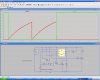
I took the output from the circuit from the area where you wrote "Out" ie between R6 and Q3.

I can't see any glaring mistakes, on either the circuit diagram or the connections, but I'm fairly tired at the moment so I could be over looking something obvious.

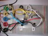
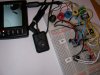
I'll attach two photos of the circuit on the breadboard to see if you can see anything, but the photos just look like a jumble of wires so I doubt if they will help..

Cheers
Al

EDIT: forget to mention with pot set at 650 ohm, turn unit on it goes into sensor mode, but after approx 4 seconds it starts recording regardless of whether of not there was motion sensed.
 

Attachments

  • JS619_pcb03s.JPG
    JS619_pcb03s.JPG
    428.9 KB · Views: 201
  • JS619_pcb04s.JPG
    JS619_pcb04s.JPG
    343.4 KB · Views: 186
Last edited:
This circuit should be exactly as the one you built the first time, but with the additions of Q1, Q2, R4 and R3. Pay very close attention to the orientation of the transistors, especially Q2, as it's going to be connected reverse of the other two. I would also suggest that you remove the additional components, build and test the circuit identical to the one already working. Once you're satisfied that the "original" design is working, then add the new components.
 
Last edited:
Once you're satisfied that the "original" design is working, then add the new components.

JS619_pcb05s.JPG

aha, I didn't realise it was mostly the same circuit.. I've totally reconnected everything, and the "original" circuit works exactly as before.

So far so good. but the addition of the extra components performed exactly as the first test, ie straight into record mode after 3-4 seconds approx and not turning off.

I've added a revised circuit diagram but no changes from yours BrownOut, just highlights the old and new components.

It could be the motion sensing is faster than 1ms I guess!!:confused:
 
So far so good. but the addition of the extra components performed exactly as the first test, ie straight into record mode after 3-4 seconds approx and not turning off


I thought you went into record mode immediately, and recorded for the perdetermined time. Can you tell me exactly how this is working?


This is what you said about the 1st circuit:

Motion, Rec 3 secs, Stop recording
 
Last edited:
Can you tell me exactly how this is working?

I figured it would be best to provide a video of the behaviour.


**broken link removed**

It doesn't make for great viewing, but gives a much clearer idea of what's going on. (sorry about the Rapidshare link but it wouldn't upload directly as an attachment in a zip file to the forum.)

I'm away for a week, but will come back to this on my return.

BTW I should have said these units are readily available on fleabay for around $124 if anyones interested in following this project through.. **broken link removed**

Perhaps you should wait to see if we can fix it first ;)


Thanks again for your time BrownOut
 
The circuit works as specified. What needs to be done is to construct it correctly, and be able to describe it's operation. Although it might work well with pin 7 disconnected, I would leave it as it is.
 
The circuit works as specified. What needs to be done is to construct it correctly, and be able to describe it's operation. Although it might work well with pin 7 disconnected, I would leave it as it is.

I tried disconnecting pin 7 but it makes no difference at all.

from bootup, the DVR goes into awaiting motion mode, and with no motion after about 4 seconds it starts recording and doesn't stop recording regardless of whether there is motion or what value the variable resistor is set to.

I've rechecked the circuit and the only suspicious area is the PNP transistor connections, simply because I'm not familar with the connections.

So correct me if I'm wrong, the 2N3904 NPN transistor and the 2N3906 PNP transistor seem to connect the same pins C-B-E where flat side down, curved side up, the left pin is C, the centre pin is B, and the right pin is E.

to-92.gif

On the circuit board the PNP Q2 connects..
to the centre pin B via a 10kΩ resistor to the trigger voltage and 555 pin 2
to the right pin E via a 1kΩ resistor to Vcc or 555 pin 8
to the left pin C to NPN Q1 pin B

which seems all in order.

Would it help if I replaced the variable resistor (up to 5MΩ) and the fixed resistor (39kΩ) with someting lower? (eg 10kΩ as Brownout's circuit)

I'm stumped, but would be more than happy to test any suggestions that may shed light on the where the problem is.

Thanks
 
Can you measure voltage in the circuit? With no motion, the you should observe the following voltages.

VCC across C1
0V at Q1 base
VCC at Q2 base

Also, try connecting a 10k ohm resistor between ground and Q1 base, especially if that voltage does not measure close to 0.

If you don't have this working by the time I return from my trip to Atlanta on Saturday, I'll breadboard it myself and see if I can get it to work.
 
Last edited:
Can you measure voltage in the circuit? With no motion, the you should observe the following voltages.

VCC across C1
0V at Q1 base
VCC at Q2 base

I may have spotted the problem..

Cell voltage = 3.79V & 4.2V (has 3 contacts)
VCC across GND & 555 pin 8 = 3.79V

VCC across C1 = 0.07V
0V at Q1 base = 0.24V no motion 0.44V with motion
VCC at Q2 base = 3.1V no motion 2.55V with motion

2.55v should be the trigger voltage, ie 0v approx, so that is where the problem is I would guess.


with the 10kΩ between ground and Q1 base there is a change in performance,

previously..
Al Chemist said:
from bootup, the DVR goes into awaiting motion mode, and with no motion after about 4 seconds it starts recording and doesn't stop recording regardless of whether there is motion or what value the variable resistor is set to.

now...
from bootup, the DVR goes into awaiting motion mode, and with no motion after about 4 seconds it starts recording and stops recording after 4 seconds, but does not respond to motion regardless of whether there is motion or what value the variable resistor is set to.


0V at Q1 base = 0.08V no motion 0.61V with motion
trigger voltage exactly as last measurements ie VCC at Q2 base = 3.1V no motion 2.55V with motion

Having just disconnected the new circuit, the old circuit trigger voltage was 0.17V which it responded to as motion detected, so the 2.55V is definately too high to be seen as a trigger voltage.

I hope that helps pin point the problem BrownOut.
 
I think I see what's going on. Q2 appears to be always on. It looks like the output from the motion detector isn't high enough to trun off Q2 when there is no motion. Please make sure Q2 is correctly connected to the motion detector and the resistor is the correct value. Then measure the output of the motion detector with NO motion. Post the measurement. I think it's going to be too low. If so, I'll make the necessary correctoin to the circuit. Thanks for reporting the measurements so far.
 
Please make sure Q2 is correctly connected to the motion detector and the resistor is the correct value.

All OK and checked ie..
Q2 Base resistor R4 = 10kΩ then connects to 555 Pin 2
Q2 Emitter resistor R3 = 1kΩ then connects to 555 Pin 8

Then measure the output of the motion detector with NO motion. Post the measurement.

555 pin2 to Gnd = 3.14v no motion, 2.55v with motion
Q2 Base to Gnd = 3.10v no motion, 2.62v with motion

Slight volt drop due to the R4 resistor I'd guess.

I don't know if it will make a difference but those measurements were taken with the 10kΩ resistor still in place between ground and Q1 base from the previous post.

Also the 555 timer is a TS555/6CN..

TS555/6CN Low Power Timer
Product Features

A low-power pin-for-pin replacement for the 555, but requiring only about one fiftieth of the supply current. The device has extremely low trigger, threshold and reset current, typically 20pA, and a very wide supply voltage range 2V to 18V. Supply decoupling close to the device is not required. The outputs are fully CMOS, TTL and MOS compatible. Choose high values for timing resistors to keep supply currents low and low values for capacitance, which should be low leakage types, not ceramic.

**broken link removed**

Again I'm not sure if that factors further complications into the mix. I chose it for it's ability to handle sub 3v voltages, with hindsight perhaps I should have worked it the other way as I believe a standard N555 doesn't see very low trigger voltages!!
 
Yeah, we have a problem with the fact the the motion detector doen't output a level high enough to keep Q2 turned off when there is no motion. I never even thought about that when I was going through this. Let me think about a possible solution. I'm in the middle of a trip right now, return on Saturday. I'll give this some thought. There is a simple solution.
 
Last edited:
Not at all. All we need is a bias for Q2 that keeps it cut off til motion is detected. Couple resistors and we'll be up and running. I just need to get back home to do it.
 
The attached circtuit adds R1, a 2.2k ohm resistor, and q4 to the circuit we've been working with. R1 pulls the base of Q2 up so that it is in cutoff when there is no motion. q4 makes up for loss in gain of Q2 because of the resistor R1. Try this circtuit. It simulated successfully with the input at the level you're using.
 

Attachments

  • retrig6.JPG
    retrig6.JPG
    127.7 KB · Views: 185
Last edited:
It doesn't appear to be working, it just sits there not seeing motion, which translates as there is a voltage permanantly on terminal 2 on the T555 I would guess.

Which if you look at the circuit, R1 (2.2kΩ) sits between terminal 8 (Vcc) and terminal 2 via R4 (10kΩ), which basically means there is a direct connection between t2 & t8 (3v+) with 12.2kΩ seperating the two, so terminal 2 is unlikely to ever see 0v.

At least that is what it looks like is happenning to me.

Removing R2 makes the DVR record in the exact same way it always does without the circuitry, ie no time delay when it doesn't sense motion.

Any ideas?
 
Why remove R2? Do you mean R1???? To say there is a direct connection with 12k ohms between is a contradition. 12K ohms is alot of resistance, so the connection is not 'direct.' If removing R1 makes the circuit 'work' then the output resistance of your motion detector is seriously high! Logic output is typically in the 50-ohm territory, and should by nothing with connected to 12 K ohms. Is it possible to measure the output voltage of the motion detector? I just can't believe it can't drive this very high resistance.


EIDT: Re-read your post. You're concerned about pin 2 reaching 0V. Don't be. It only has to get to VCC/3. In this case, 1.3V. It should make that easy, if the output impeadance of your detector is reasonable.
 
Last edited:
One more thing, take a jumper and quickly temporarily gound pin 2 and tell us what happens. Thanks.
 
Last edited:
Status
Not open for further replies.

Latest threads

New Articles From Microcontroller Tips

Back
Top