ElectronicsDevil
New Member
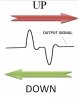
I have a pulse as a input of a counter will u plz suggest me the counter design.
The ckt should work like this:
when the is first positive and then negative it should up count
when the is first negative and then positive it should up count
PLZ ONLY USE FLIPFLOPS

The ckt should work like this:
when the is first positive and then negative it should up count
when the is first negative and then positive it should up count
PLZ ONLY USE FLIPFLOPS