Continue to Site

Welcome to our site!

Electro Tech is an online community (with over 170,000 members) who enjoy talking about and building electronic circuits, projects and gadgets. To participate you need to register. Registration is free. Click here to register now.

  • Welcome to our site! Electro Tech is an online community (with over 170,000 members) who enjoy talking about and building electronic circuits, projects and gadgets. To participate you need to register. Registration is free. Click here to register now.

FLED-based solar engines

Status
Not open for further replies.
It appears they are being used in the same way as a unijunction transistor; something that will trigger a circuit once a certain voltage is reached.

You can use two normal transistors to give a similar effect:

transistors-negative-resistance-dvices-electronics-world-june-1969-9.jpg


When the emitter of Q1 reaches a point around 0.6 - 0.7V higher than the base voltage set by the voltage divider at the base of Q1, the transistors work rather like a thyristor and latch on, until the capacitor discharges.

I'd put a load resistor between the emitter of Q2 and ground, so the transistors are not just short-circuiting the capacitor and taking a high current pulse.


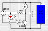
The original LED circuit is also a bad design with a similar flaw, as the capacitor is being short circuited by the left hand transistor and through the base of the right one.
Adding a series resistor to limit the base current would allow much more of the stored energy to be used by the motor.
 
Can't I just use zener diodes?
That depends on the current from the solar panel.

If it's high enough that the current drawn before the circuit actually switches does not prevent the capacitor still charging, a zener should be fine; however if it's supposed to be a micropower circuit that draws next to zero zero current and can charge very slowly, a better, more sensitive trigger would probably be needed.
 
Do you think a resistor like the one I added in the attached image will be ok?
In case I will use a zener diode, should I go for a 2.4V one?
 

Attachments

  • beam1.png
    beam1.png
    9.4 KB · Views: 177
Last edited:
Why not look at the many other circuits on the same site?, or simply buy the easily available flashing LED - unfortunately such designs are from many years ago and used fairly obscure IC's in strange ways.
 
Do you think a resistor like the one I added in the attached image will be ok?
In case I will use a zener diode, should I go for a 2.4V one?
It may work; but, as it starts to conduct, the motor will progressively be drawing current and may well prevent the capacitor from charging further.
 
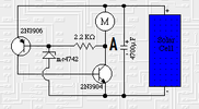
I have find a zener version of the circuit.
I have a question: is voltage in A point different from zero only when the motor runs?
I cannot understand how the FLED or the Zener diode can reach a voltage to trigger the circuit.
Thanks
 

Attachments

  • beam2.png
    beam2.png
    9.2 KB · Views: 167
The motor will have a very low resistance, so point A will be pretty much the same voltage as the cap and solar cell positive, until the lower transistor turns hard on and runs it.

The "trigger" point is supposed to be when the capacitor voltage reaches about 0.6V more than the zener voltage, so current passes through the base-emitter junction of the left transistor and starts that turning on.

I can't get a simple circuit such as that to work, in simulation at least.. There are many far better circuits that will not give such problems, as Nigel says.
 
Yeah, something like this:
In the video I think he's using normal LED. He covers it from light.
Why?
 
Why cover them from light?
Possibly to reduce the leakage current?
LEDs also behave as photodiodes, to some extent; producing a small current when exposed to light, or starting to conduct in reverse when illuminated.

Or just as they don't want the "trigger" device showing...
 
most likely its just a led that flashes, it looks like the energy from the motor causes the trigger then cuts off at a certain point, causing each twitch in motor and led. the more light the more pulses per second, but the circuit config holds each pulse to a similar amount of time
 
Status
Not open for further replies.

New Articles From Microcontroller Tips

Back
Top