Continue to Site

Welcome to our site!

Electro Tech is an online community (with over 170,000 members) who enjoy talking about and building electronic circuits, projects and gadgets. To participate you need to register. Registration is free. Click here to register now.

  • Welcome to our site! Electro Tech is an online community (with over 170,000 members) who enjoy talking about and building electronic circuits, projects and gadgets. To participate you need to register. Registration is free. Click here to register now.

Electronic relay/ Capacitors and Motor identification hookup unknown?

Status
Not open for further replies.

BCurtis

Member
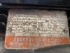
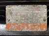
To Start I have a Mode 5KC184AL2050 (which I can find Zero Info on).
3HP/230VAC/17Amp
Frame 184T/Cont Duty
Conndiag 733A350

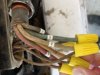
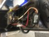
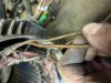
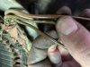
There are 5 wires at motor, three are windings I believe L1or(11)possibly common? 5&6, then 1&4 (centrifugal switch I believe?) these 5 wires then go up to a termination box with what I think may or may not be a solid state relay? There's 2 capacitor's wired in series, as well 230V supply.

I'm not able to find wiring diagram and model number gets me nowhere ugh.

Is there anyone out there that is familiar with this type of motor? What type of induction motor? Wiring diagram? What is electronic's tied to centrifugal switch relay? not able to find this S4 Power device model C20 anywhere either

The way it runs was in reverse so I swapped 5 and 6 at motor, direction changed but I smoked a capacitor (415 to 500mF) I replaced and now the other cap is starting to smoke. Wiring at motor is odd to me and really struggling with this.
Thanks everyone
 
It's most likely something like this:

ep_2e_19-28.jpg


With only the "run" winding on single phase, it would not start - there is nothing to define which direction it should run.
The capacitor and start winding produce an offset field to give a rotational direction.

The "start" capacitor allows high torque for startup, but is not appropriate for full speed, so that is disconnected once the motor is running at a decent speed, by some device - a centrifugal switch to sense motor speed in your case.


Some types have the start and run windings symmetrical and can be reversed by swapping them over, but in others the start winding is lower rated and they are not interchangeable.
To reverse that type I believe you have to re-link the winding so the phase of one is reversed relative to the other, if it's built so that is possible.


Some pictures of the terminal box or connections may help?
 
Thank you rjenkinsgb!
This motor has 2 caps wired in series though the diagram above they are in series(5 leads at motor (2) centrifugal switch and (3) for windings.
At terminal box there’s a electronic relay maybe? For centrifugal switch I believe.
Pics attached
 

Attachments

  • 36EA653D-DB79-4B12-A2B9-5D38D64C3ED2.jpeg
    36EA653D-DB79-4B12-A2B9-5D38D64C3ED2.jpeg
    27.7 KB · Views: 134
  • 0FAA76B8-8E6E-42A3-AA91-27EF69CB5DA7.jpeg
    0FAA76B8-8E6E-42A3-AA91-27EF69CB5DA7.jpeg
    25 KB · Views: 161
You can sometimes reverse a motor without changing any connections, you can do it physically.
You strip the motor down then reverse the orientation of the corepack (the bit with the windings in), put it back in the other way around.
The electrical rotation will be the same, but because the core is back in the opposite way around the shaft will rotate the other way.
I've done this with motors that had the windings internally connected, you need to make sure though that theres no offset or difference in the position of the core laminates or you could fry the motor.
 
Dr.peper does this mean on this type of motor windings cannot be reversed at terminals?
Is there a chance a drawing is out there? I don’t have one and model number gets me nowhere.. and very hard to read
 

Attachments

  • C8B0FF00-DCB7-42A3-AF3B-3DE4068546E3.jpeg
    C8B0FF00-DCB7-42A3-AF3B-3DE4068546E3.jpeg
    32.1 KB · Views: 146
Generally the start capacitor is bi-polar electrolytic, if so, if in circuit for more than a few secs, it will destroy it.
The run capacitor is often oil filled paper and can be connected in circuit permanently.
Not likely they are in series.
If no internal centrifugal switch, then often an exteternal current relay is used for the start cap/winding.
The lowest resistance winding, is the run winding.
Max.
 
This looks interesting - the two diagrams in the centre of the first page are for GE "KC" type motors, five wire with numbers similar to yours..
**broken link removed**

Looking at the centre one with the 9 terminal switch, it appears live is always to 4 and neutral to 6.
For one direction, live links to 1 and 5-6 are joined, for the other direction live links to 5 and 2-6 are joined.

I'm guessing the motor was originally designed to have the capacitors attached to its body and permanently wired to certain terminals, along with the centrifugal switch?

Does that seem to fit in with the way it was wired when it ran OK?
 
Nope it doesnt mean it cannot be reversed with the wiring, it was just an alternative suggestion to thiink of if you were struggling with the electrics.
 
Even though all of the wires from the motor are brown, it looks like the insulation is individualy numbed. e.g. T2 etc,

Those are standard terminal numbers.
 
What does the writing on the black box your calling an "electronic relay" say? It could passably be a "potential relay". Commonly used with sealed refrigeration compressors, but sometime used to replace a bad centrifugal switch in an otherwise good motor. Knowing what the writing says would tell more about the "electronic relay".
 

Attachments

  • Potential_Relay.pdf
    733.7 KB · Views: 192
I have seen another way used to switch out the start winding when the motor gets to near it's design speed. It uses a relay with only a few turns of thick wire for the coil which is connected in series with the main winding. When the motor is stopped or running below it's normal speed the main winding current is much higher than normal so the relay pulls in energising the start winding. when the motor is up to near normal speed the current drops so the relay drops out removing the power to the start winding.
BCurtis,
You say in post #1 that there are two capacitors connected in series. Can you confirm that there is nothing else connected to the junction of the two capacitors and also tell us what the value (Capacitance) and voltage rating of the capacitors is and whether the rating is for AC or DC ? can you post better focused pictures than in post #3 and copy ALL the information from the plate on the motor ? (I don't think we could read this even if the picture was better focused.

Les.
 
Last edited:
Gents I pulled motor apart in hopes to understand what type of motor I’m dealing with, found that all windings are the same size which is confusing to me.
#1,6,(L1) 11 are on bottom of one side and 4,5 come out on opposite side (top).
I’m quite stumped with what type of motor this is and no idea on how to wire without diagram.
Could it be that there’s 2 run windings, 1 start winding with electronic relay and 2 caps wired in series for start winding? (230V)
Added couple more pics. I’m just adding this and will be reviewing all comments I missed after pulling motor apart.
 

Attachments

  • B1420F8C-8885-48C2-9D62-3C6C3F3D7E75.jpeg
    B1420F8C-8885-48C2-9D62-3C6C3F3D7E75.jpeg
    27.7 KB · Views: 162
  • 9C7F3C6F-062B-4C8D-BE54-9ADABA377183.jpeg
    9C7F3C6F-062B-4C8D-BE54-9ADABA377183.jpeg
    25 KB · Views: 145
  • 03D47CE5-6B0C-41A7-95EA-242A7A1CD933.jpeg
    03D47CE5-6B0C-41A7-95EA-242A7A1CD933.jpeg
    28.8 KB · Views: 146
  • CE44914D-2807-4635-888B-F82A38B46B53.jpeg
    CE44914D-2807-4635-888B-F82A38B46B53.jpeg
    28.8 KB · Views: 130
  • 0C89953A-51AF-4B5C-AC56-EBAF921F6EE2.jpeg
    0C89953A-51AF-4B5C-AC56-EBAF921F6EE2.jpeg
    33.8 KB · Views: 132
CAPs are 440-516mF, 110-125VAC and strangely were wired in series 100%. Wire#8 into cap and wire#9 out of second cap.

it is a GE Triclad Induction motor.
3HP, 230VAC, 17A, Cont Duty, Type KC, Frame 184T
Model number: 5KC184AL3050 (zero info out there that I could find)
There’s bearing numbers on name plate for both ends of motor which tells me age is up there because it’s maintainable.
On name plate also has “conndiag#”
Which I interpret connection diagram??
# is 733A350 but I’ve found zero info on as well.
The electronic potential relay is in pics and I find zero info on as well. It has 2 black wires that I feel are coil inside ? And opposition side is a red/white which I believe to be contacts open/closed. ( no power as device sits contacts are open tho another confusing thing to me) but without diagram hard to say if it’s correct/good/damaged etc?
Just another note there is no centrifugal switch I was confused on this above but as you gents said that’s what electronic relay (S4 power Device, model c-20) is for sorry this thing has me quite confused and worked up ha.
 
I would like to add one more thing because my findings when opening motor and found all windings are exactly the same size wire, when ohming out there’s no high resistance on any of leads like a start winding would usually have ...would this be why the 2 caps are in series and such a high rating? And possibly 2 run windings without caps?
 
Ok thx MAX, all great info so my understanding is you would think in my situation the relay I have would be “current” sensing hence contacts open .
 
As the motor is a 230 volt motor and the capacitors are only rated at 120 volts the person fitting them probably did not a have a 230 volt rated capacitor so he used two 120 volt capacitors in series. NOTE If you fit a single 230 volt capacitor it will only need to be about 220 - 250 uF. (As two capacitors of the same value in series have half the capacity value.) If I was replacing the capacitor I would order a capacitor with an even higher working voltage than 230 volts. Note the capacitor must be rated for AC.

Les.
 
Status
Not open for further replies.

Latest threads

New Articles From Microcontroller Tips

Back
Top