Continue to Site

Welcome to our site!

Electro Tech is an online community (with over 170,000 members) who enjoy talking about and building electronic circuits, projects and gadgets. To participate you need to register. Registration is free. Click here to register now.

  • Welcome to our site! Electro Tech is an online community (with over 170,000 members) who enjoy talking about and building electronic circuits, projects and gadgets. To participate you need to register. Registration is free. Click here to register now.

Electronic relay/ Capacitors and Motor identification hookup unknown?

Status
Not open for further replies.
Evening guys I attached the orientation of everything because I’m still battling.
I’m just working on tryin to get a 12vac supply to figur this relay out.
There’s 15meg ohms between red/white and blacks are open.
I labelled what I feel I’ve found with wiring and windings.
Thoughts? From drawings you gents are working with it’s just not clicking in my head and feeling like I’m not a electrician and lost all confidence I’ll figure this out even with your help lol
 

Attachments

  • 15601D4B-37D0-47F2-9A48-9506B5A14403.jpeg
    15601D4B-37D0-47F2-9A48-9506B5A14403.jpeg
    1.6 MB · Views: 109
I do not agree with the labels you have put on the drawings on posts #42 and #43. I believe that L1 to 6 is the start winding. L1 to 5 is one half of the run winding and 1 to 4 is the other half of the run winding.

Les.
 
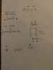
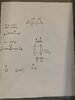
Ok fair that’s why I’m asking, can u explain why 1&4 are a larger wire and are metering connected to each other. (3ohm)

5,6,11 are small wires and meter connected to each other. (3ohm)

and the two sets have no connection to each other when wiring is all open

looking at drawing in post 34 I’m must be missing wire numbers to understand the 230v
 
I don't know why wires 1 & 4 are thicker than the other 3. Is the missing wire number in the two 230 volt diagram wire 6. If so it is the other end of the start winding to it's L1 end. (6 is the end of the start winding that connects to one of the capacitors.) Are you saying that all three resistance readings 5 to 6, 5 to 11 and 6 to 11 are all 3 ohms ? This is the first time wire 11 has been mentioned so we now need to work out how this changes the diagrams reasoned out in post #34. Also in post #31 you say the resistance between 1 and 4 is 2 ohms. which reading is correct ?

Les.
 
That’s correct on everything you said wire 11 I have mentioned it’s just labeled L1 and 11. But certainly have left out in a couple post or wrote it like “L1(11)

sorry about confusion

so metering:

1 to 4 is (3ohms) Common to each

Below are all(3ohms) Common to each
5 to 6
5 to L1(11)
6 to L1(11)

There Is no physical ohm connection between the 2 groups tho
 
After writing post #46 I noticed that the second drawing in post #34 was wrong (Labelled 230V one direction) I had drawn it feeding the start winding circuit with 230 volts rather than tapping off 115 volts from the junction of the two main windings.
190520.jpg

The top drawing above shows how I intended to draw it. The second drawing is an alternative way. This has the advantage that to reverse the direction the bottom end of the contact on the start relay just as to be swapped from the mains L1 to the mains L2. (As mentioned by rjenkinsgb in post #35.)
I don't understand how the windings are connected from the three 3 ohm readings. It could be a short between winding with the burned out winding that dr pepper noticed in post #39.

Les.
 
I’ll give this a go!! The start relay has me stumped I wasn’t able to figure 12vac supply so tried 120vac but seen no change in any way wired..
Red/white wire have 15mohms between them and black wires are open and don’t seem to change state in any configuration (OL) originally tied together.
Thx Les I’ll let you know how it goes a huge thanks !
 
Can you take the six resistance measurements between the four connections on the start relay. Mark the two black wires wit labels 1 and 2.
Take these resistance measurements and report the results
Black 1 to black2
Black 1 to red
Black 1 to yellow
Black2 to red
Black2 to yellow
Red to yellow.
This may give us enough information to understand what is inside it.

When you have worked out a way connect the run windings in series with the correct phasing you could try energising the start winding for a second or so using a manual switch. Until you find a low voltage AC source to do the phasing test you cannot proceed.

Les.
 
Les
Red to yellow(white) = 15mohms
The remaining measurements are all open
(OL) as mentioned couple times.
As well mentioned when 120vac put on relay no change.
 
From those readings the "relay" is either faulty or some type of electronic start switch. If it is an electronic start switch then without the manufacturers data it is not useable. I suggest testing the motor using a manual start switch when you have sorted out how to connect the two start windings in series WITH THE CORRECT PHASE RELATIONSHIP.

Les.
 
Sounds good Les
I feel your correct 100% unfortunately no info on switch I did send picture through post.
It seems I’m working against brick wall and why I’ve called GE , researched etc and nobody but the gents on this forum have been helpful! SO THANK YOU ALL for your assistance though I haven’t won yet I will keep trying your suggestions
 
Well les GE still hasn’t returned my calls after 1/2 dozen messages.

ive hooked motor up but not able to leave running as it’s drawing 75amps and feel caps aren’t dropping out and going to smoke..

White of relay to #8 of cap
Red of relay to #4 and L1 (120vac)
The two blacks of relay to #11 of motor
#9 of cap to #5 of motor
#6 and #1 of motor to L2 (120vac)
 
Forget about the "relay". I think it is probably faulty even though we don't know how it was designed to work. Just wire it up as in either drawing in post #48 bypassing the coil part of the way I have drawn the start relay and wire a normal switch in place of where I have drawn the relay contact. With this switch in the closed position switch on the power and then switch the switch that is in place of the relay contact to the open position after about one second. The motor should have started during that period of one second and opening the switch disconnects the start winding and start capacitors as thy are no longer required when the motor is up to speed, If this does not work then the motor is faulty. Almost certainly due to the winding that looks like it is burned out.

Les.
 
Ok I’ll give than a go but the #11 wire will have nothing wired to it that way as both blacks from relay/coil go to it.
Basically I tried wiring the way you presented to me but motor doesn’t turn on.
So I hooked everything upas I originally found it and motor runs just caps don’t drop out.
They way it was wired really doesn’t make any sense to me but it’s the only way it runs as well the way it always ran.
 
I will refer to the second diagram in post #48. Where I have drawn the relay coil between the mains L2 and your connection number 1 you will now connect the mains L2 to your connection number 1. You will now connect your switch in place of the relay contacts that connected to the wire from the capacitor and mains L1. Mains L1 will still also be connected to your connection number 5. I am assuming that you are in the US or Canada where I think the terminology used is that L1 and L2 are both 115 volts with respect to the neutral wire (Which is nominally at ground potential .) but L1 and L2 are in anti phase with each other so there is 230 volts between them.

Les.
 
Understood Les:)

and that’s correct in Canada where :

L1 to ground or neutral is 120vac which is known as 115V
L1 to L2 is 240 vac known as 230vac.
 
Les..

so running the way it was with switch in replacement of relay:
Switch on: 75Amp Switch off: 12Amp
Then:
Your last diagram:
Switch on: 33Amp Switch off: 5Amp

motor amps on tag is 17amp
 
I have no idea of the way it was wired when you say " the way that it was" Can you post the drawing of " the way that it was" . I think 75 /12 amps is too high.
I am assuming when you say my last diagram you mean the second diagram in post #48. If so then 33/5 amps seems reasonable. (The 17 amp rating will be for the motor running under full load.) I have never measured the start and run currents of capacitor start motors and have never had a faulty one. (The largest one I have is 1.5 HP driving a compressor.) It is over 50 years ago that I worked with larger motors and they were all three phase. You will now need to find a suitable start relay.

Les.
 
Status
Not open for further replies.

Latest threads

New Articles From Microcontroller Tips

Back
Top