Continue to Site

Welcome to our site!

Electro Tech is an online community (with over 170,000 members) who enjoy talking about and building electronic circuits, projects and gadgets. To participate you need to register. Registration is free. Click here to register now.

  • Welcome to our site! Electro Tech is an online community (with over 170,000 members) who enjoy talking about and building electronic circuits, projects and gadgets. To participate you need to register. Registration is free. Click here to register now.

Electronic relay/ Capacitors and Motor identification hookup unknown?

Status
Not open for further replies.
Ok thx MAX, all great info so my understanding is you would think in my situation the relay I have would be “current” sensing hence contacts open .
Normally they would be open, it is the start current that closes them via the current coil. Untill up in run.
Max.
 
Now that you have removed the end caps from the motor have you confirmed if it does have a centrifugal switch ?

Les.
 
Rjenkinsgb I’ve attached the way it was wired, to me the electronic switch isn’t doing anything. And really makes very little logical sense ? The second pic is how I feel it should maybe be wired but still struggling because windings are same size, resistance of them are all so low and no indication on which winding is which..
 

Attachments

  • C5E904A4-39F0-489C-9C12-41E652EF41C1.jpeg
    C5E904A4-39F0-489C-9C12-41E652EF41C1.jpeg
    113.4 KB · Views: 108
  • 3E21CE86-311F-44D3-B923-8E888400ABC0.jpeg
    3E21CE86-311F-44D3-B923-8E888400ABC0.jpeg
    57.3 KB · Views: 97
There is no centrifugal switch after pulling motor apart as mentioned, I feel electronic cut out maybe no good in return will not drop caps causing them to smoke oil out.. but is weird that the way it was wired everything worked. Windings are my battle if I don’t know what’s what with the 5 wires, it’s hard to have a starting point on where to install relay in correct spot. Relay shows open between red/white which indicates failed I believe and opposite end with two blk wires as open but believe this is right being coil end. Hope this extra info helps
 
From the second diagram in post #25 I think the motor may be an American dual voltage motor. The main winding is split in two so it can be connected in series for 240 volts or in parallel for 120 volts. When connected for 240 volts (As in the diagram the main winding acts as an auto transformer to supply the start winding with 120 volts. (This avoids having to change anything on the start winding when changing voltages.) I think the unknown relay device should have it's coil connected in series with the main winding. I suspect that two of the wires on the relay will read a very low resistance between them. I suggest that you measure the resistance between all 4 wires from the relay to see if this theory is correct.

Les.
 
LES thank you for this information! I will be measuring resistance of everything today again. There’s been a lot of info come my way and all good but getting confused now ha.
I’ve tried drawing what I thought would be right numerous times and I get stumped. Wish I could just find the correct drawing for the configuration of motor I have before I fry the thing.
 
Resistance of windings:
All wires to ground (L1,1,4,5,6) = Open
6 to L1= 2.6 ohm
1 to 4= 2 ohm
L1 to 5=2 ohm
The remainder of connections are open and do not have continuity.
 
OK, I'd say that is dual voltage, non-reversible (at least in low voltage configuration).

L1 - 5 is the run winding (& direct power across those).

L1 - 6 is the start winding.

1 - 4 is a second run winding, to be linked either in series with L1 or parallel to L1-5 depending on the supply voltage.

If it's in series with L1 for high voltage, the start/run direction could be set by which power feed wire the cap to 6 is connected to?
 
Rjenkinsgb
So this motor is 230v but start winding has to be 115v because the caps are wired in series.
So still reversible you think?
I’ll try drawing your configuration out adding caps/relay in.
 
I agree with Rjenkinsgb 's conclusion. (Post #32) From your reply in post #33 I don't think you fully understand what Rjenkinsgb has said. The motor can be wired to work on either 230 volts or 115 volts as Rjenkinsgb said (And I said in post #28.) The start winding in series with the capacitors and contacts on the start relay will be fed with 115 volts in both cases. When wired for 115 volts the start winding in series with the capacitors and contacts on the start relay is directly across the 115 volt mains input. When connected for 230 volts the 115 volts comes from one of the run windings which are connected in series. (So each run winding will have half the supply voltage across it.) As one end of the start winding is internally connected to one end of one of the start winding the phasinf between these cannot be changed. (Unless you are prepared to dig into the winding terminations to separate the ends of these windings.)

100320.jpg

Yo may have to swap over connections 1 & 4 to get the correct phase relationship between the two run windings. I have drawn the start relay assuming it works by sensing the current in the run winding. I suggest that you check this by connecting 1 to 5 and applying a low AC voltage (Say 12 volts) between L1 and 5 and measuring the voltage between L1 and 4. The measured voltage should be about twice the applied voltage. If it is not then swap over the connections 1 & 4 and measure the voltage between L1 & 1. You will need to make resistance measurments of your start relay or dismantle it and post pictures.

EDIT. I have noticed that I have made an error in the second circuit. The feed side of the contacts on the start relay should be connected to the junction of the two run windings (Connections 1 and 5) NOT the L" mains input.

Les.
 
Last edited:
I was envisaging it as your third diagram.

Wired like that, it should be possible to select either direction purely by changing the start contact / feed to the capacitors between either L1 or L2 supply, I believe?

No other re-arrangement required?
 
Gents I’m overwhelmed with this and can’t thank you all enough!! I’m not ignoring and will review/respond!! Something came up in life that needed my immediate attention. I will be back as soon as I possibly can.
Thank you all for the continuous troubleshooting!!!
 
Hi rjenkinsgb,
I realised that the third circuit was the better option after drawing it as only a single pole changeover would be required for reversing.
 
Hey guys after unpredictable events I had to leave this and apologize I didn’t thank you all for your help!! So THX!
I did get motor apart and put back together last night.
I feel I’m going to start fresh and read all your posts then proceed to hook up and test.
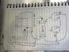
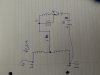
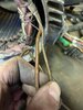
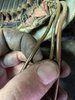
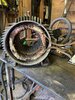
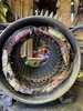
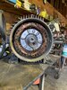
I did attach couple winding pictures though I said I was going to 2 plus months ago there they are.
1, 6, 11 (L1) come from bottom of motor,
5, 4 come from top of motor,
1 &4 (Larger wires)
5, 6, 11 (L1) (smaller wires)

not sure if orientation, size helps determine drawing to hook this up but it is a touch more info that was asked about.
Thanks
 

Attachments

  • DC0309DB-8470-49D7-B6F4-911A961CFD98.jpeg
    DC0309DB-8470-49D7-B6F4-911A961CFD98.jpeg
    1.6 MB · Views: 121
  • 26F4869B-67E3-4DE0-B2F2-7F9AEF2CCA9F.jpeg
    26F4869B-67E3-4DE0-B2F2-7F9AEF2CCA9F.jpeg
    1.5 MB · Views: 111
  • CB0A8548-25CA-41FB-BF27-A7F32655EF06.jpeg
    CB0A8548-25CA-41FB-BF27-A7F32655EF06.jpeg
    1.8 MB · Views: 114
  • 5B3E3A86-E986-4FF5-9095-472C3A465B08.jpeg
    5B3E3A86-E986-4FF5-9095-472C3A465B08.jpeg
    1.7 MB · Views: 116
  • EAA8767C-03AE-4084-A64F-5B48964E8E77.jpeg
    EAA8767C-03AE-4084-A64F-5B48964E8E77.jpeg
    1.8 MB · Views: 112
I agree with dr pepper that one winding looks VERY overheated. Unless the motor is a special design to fit a specific machine (For example some Bridgeport milling machines.) then it is probably cheaper to buy a new motor than getting it rewound.

Les.
 
Status
Not open for further replies.

Latest threads

New Articles From Microcontroller Tips

Back
Top