Continue to Site

Welcome to our site!

Electro Tech is an online community (with over 170,000 members) who enjoy talking about and building electronic circuits, projects and gadgets. To participate you need to register. Registration is free. Click here to register now.

  • Welcome to our site! Electro Tech is an online community (with over 170,000 members) who enjoy talking about and building electronic circuits, projects and gadgets. To participate you need to register. Registration is free. Click here to register now.

Dumore D3 dental lathe restoration project

Status
Not open for further replies.
Dear friends of the forum,
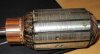
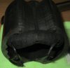
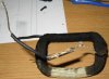
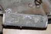
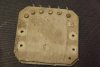
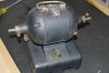
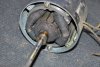
I recently picked up from a flea market for 5.00 $ a little Dumore D3 dental lathe made in 1938 !!! I started restoring it because upon inspection at home I noticed that the main cable was damaged and there is no ground at all; the engine works but I would like to restore it and modernize it a bit.
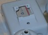
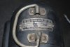
First off, the label says " Type D3 N0. 2676 Volts 115 Watts 250 full load speed 5000 RPM 1/6 30 min rating " now, it has a little know to select the speed, and it is double shaft. Upon taking it apart it had a cylinder wrapped in tiny metal ( I guess a resistance???) that was falling apart and some "thick sheets of paper and wax like material " what is it???
Could you guys help me restore it and make it safe? Pics are to follow.
 

Attachments

  • 1.jpg
    1.jpg
    94.6 KB · Views: 157
  • 2.jpg
    2.jpg
    87 KB · Views: 147
  • 3.jpg
    3.jpg
    114.1 KB · Views: 160
  • 4.jpg
    4.jpg
    75.9 KB · Views: 147
  • 5.jpg
    5.jpg
    72.9 KB · Views: 162
  • 6.jpg
    6.jpg
    135.2 KB · Views: 150
Last edited:
more images of the shield and motor ( It is a brush motor with little cilynders full of oil to lubricate the bushing-bearing
 
it had a cylinder wrapped in tiny metal ( I guess a resistance???)
Correct.
That looks like a wirewound resistor.


some "thick sheets of paper and wax like material " what is it???
That looks like a wirewound resistor with several tapping points (the brass studs).
That is a primitive speed controller, there should have been a wiper contact attached to the knob which selects the "speed numbers".
That wiper would contact the brass studs to vary the resistance and hence the motor speed.

JimB
 
I recently picked up from a flea market for 5.00 $ a little Dumore D3 dental lathe

Oh goody! DIY dentistry! Well only answer question about how to restore it if you promise to ask questions mid-procedure as you do home dentistry.
 
"Mmmpfhh the <gurgle & spit> wire-wound resistor, and connect the "Yaaargh, dammit!" to the brass contact."
<Grabs the 'dentist's' crown jewels> "We're not going to hurt each other any more, are we?"

;)
 
Correct.
That looks like a wirewound resistor.


That looks like a wirewound resistor with several tapping points (the brass studs).
That is a primitive speed controller, there should have been a wiper contact attached to the knob which selects the "speed numbers".
That wiper would contact the brass studs to vary the resistance and hence the motor speed.

JimB
Thank you JimB,
there was a wiper device as well, I just didn't take a picture of it. You think I can replace the wirewound resistor with a modern one ( the only info on it says 140 ohm) which one should i get to replace it? I want to replace it the speed "selector too and use a potentiometer to regulate speed. But how would I go about that???
 
I'm also planning on replacing the wire field around the shield as wires are covered with like " cloth material" and falling apart, the metal also it is not copper but it is grey, maybe lead???
 
more pics of the teardown process
 

Attachments

  • 9.JPG
    9.JPG
    1.5 MB · Views: 115
  • 8.JPG
    8.JPG
    950.8 KB · Views: 123
  • 10.JPG
    10.JPG
    1.1 MB · Views: 119
  • 11.JPG
    11.JPG
    1.9 MB · Views: 129
The field coil wire will be copper, but most likely tinned copper, it is quite common and was used even more with early cables as bare copper reacted more with the materials used for insulation.

The insulation is a wrap of cotton thread. It was used for "magnet wire" before plastic insulation was developed.
Or two wraps of cotton in the case of DCC wire - Double cotton covered..

You can actually still buy the stuff for renovating old gear - https://www.wires.co.uk/acatalog/dc...QrTtCh08Owv9EAQYASABEgJjbPD_BwE#adc0450_2d10m

ps. I'd dispose of that speed switch, or soak it in oil or something to prevent dust particles if you want to keep it for dimensions - it appears to be built on asbestos board.
 
Thank you friends for all the help and suggestions. I am afraid that those resistors are indeed asbestos board; I plan on getting properly dispose of them and modernize the little device. What king of wire-wound resistor should I replace the old one with? The old one just says 140 Ohm on it. I was planning on rewiring the armature shield coil with new copper wires and then use varnish as insulator, would that work? and what thickness of copper-wire should I use? I am unsure on how to connect the wires to the speed controller ( planning on getting a 20th century one install along with a ground cable.
In the mean-time I painted the shell ( sanded, primer and two coats of paint and clear-coat.)
 

Attachments

  • 14.JPG
    14.JPG
    1.7 MB · Views: 118
  • 15.JPG
    15.JPG
    1.7 MB · Views: 113
  • 16.JPG
    16.JPG
    520.9 KB · Views: 124
  • 17.JPG
    17.JPG
    1.8 MB · Views: 117
Ohh, the original paint looked so nice - like a survivor. The new restoration trend is to clean up the surfaces as well as possible, and call it a day. No fresh paint unless you can find the replica paint.). No need to regret the past, it is painted and looks good. Just something to think about for the next restoration.
 
Ohh, the original paint looked so nice - like a survivor. The new restoration trend is to clean up the surfaces as well as possible, and call it a day. No fresh paint unless you can find the replica paint.). No need to regret the past, it is painted and looks good. Just something to think about for the next restoration.
I thought it was a good idea to paint it again, that color reminded me of machinery shops ! Oh well, lesson learned, guess I'll try to stay close to original paint next time,
 
what thickness of copper-wire should I use?

Unwrap the cotton from some of the old field coil and measure the bare wire with a micrometer or vernier caliper.
Try in a few places to makes sure it is consistent.

You need to use exactly the same diameter of copper as was originally used if possible, with the same number of turns in the coil.


You may not need any extra resistors if you are using an electronic speed controller; the motor should be configured as it would be if the speed switch was set to maximum, then the electronics take care of reducing it.
 
(RWF) RH250-140-1 ,

RH250 Resistor, 140 Ohm, 250w
Is that the correct one for my engine? I know the wirewound resistor just says 140 ohm, but since the engine says 115 v 250 watt would that one be a correct one??? Sorry but not very good with electric ( and it's 55$ !!!)
 
Are you planning to use a modern speed controller?

If so, forget the resistors!

If you want to recreate the old switched-resistor system, you will need several very large and high powered resistors and it will cost far more.

The asbestos mat with the switch studs was itself a large wirewound resistor with multiple tappings - and with the original design some parts could have happily run near red hot, but you cannot use conventional resistors in that manner, it would need the open wire resistor unit recreating using nichrome wire on a heatproof former.

Using conventional power resistors that have a finite operating temperature limit, the resistors would likely take more space than the motor...
Actually, after thinking about it and your prompt, I have decided to go with a modern speed controller. I would like one that could potentially fit inside the casing of the motor with a little rotating knob in the place where the old one was; now which one would work for the kind of motor I have? can you please tell me the characteristic/features I would have to look for please?
 
Status
Not open for further replies.

Latest threads

New Articles From Microcontroller Tips

Back
Top