Continue to Site

Welcome to our site!

Electro Tech is an online community (with over 170,000 members) who enjoy talking about and building electronic circuits, projects and gadgets. To participate you need to register. Registration is free. Click here to register now.

  • Welcome to our site! Electro Tech is an online community (with over 170,000 members) who enjoy talking about and building electronic circuits, projects and gadgets. To participate you need to register. Registration is free. Click here to register now.

Digital keypad 1-12 will this work ?

Status
Not open for further replies.
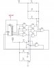
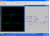
Take a look at this schematic, the idea is to charge caps to hold transistors and get an "and" output in the end. A wrong pushed button shunts the caps. Just wanna know if it will work the way I want it too.

I could put pull down resistors in to drain the caps in about 1.0sec so they would have to do it fast.
 

Attachments

  • Digi keypad.JPG
    Digi keypad.JPG
    45.7 KB · Views: 292
Last edited:
The basic logic looks ok if you add some stuff to make it functional. Like some r's to limit the charge current and some more to limit base current. Maybe some to discharge the caps and turn the transistors off after a while. The output low may be .6 to .9 volts if that's ok.
 
Thanks ronv, I wanted to charge the cap fast and add discharge resistance so if it took someone too long they would have to start all over again. Maybe 2.0 seconds each, not doing the math maybe a 5K ??? [ R X C = T ] Because the charge current will only be momentary, about .5s from each push button. The output low would be fine. Besides when the output goes off the page I have it going to a PCB relay which will latch by a holding contact and the other two leads ya see coming back are from another set of shunting contacts on the relay which isnt shown, so they will be discharged all the way and the system relay will take over. Not to shabby for an electrician huh ? Lol, Im proud of myself because I thought I was gonna have to go with a key switch to arm and disarm the system. Its either gonna be a lock or an alarm system.
 
Lock

Very clever circuit. If you added jumpers for the numbers you could change the combination.

Here are some values that come close to what you are thinking. I added a transistor to replace the relay.. might be cheaper.

3 drawings:

Schematic
Normal operation simulation
wrong number simulation.
 

Attachments

  • Lock.PNG
    Lock.PNG
    71.9 KB · Views: 181
  • Right.PNG
    Right.PNG
    76.2 KB · Views: 185
  • wrong.PNG
    wrong.PNG
    78.1 KB · Views: 157
you can design it using a counter and with few logic gates so that it will require a sequnce too ( order in which the key has to be pressed)

Edit: attached circuit will give an out put only when S1,S2,S3 are pressed in the order.
it can be configured up to 9 digits.....no one can break the code :)
 

Attachments

  • 3 digit code lock.JPG
    3 digit code lock.JPG
    32.2 KB · Views: 204
Last edited:
always room for improvement !!! thanks, i tested it all which ways and only the pre set code worked. its pretty neat, thanks for all yer extra ideas, they helped. its for my alarm, next im gonna post one time delay zone for entry and one 24 hour zone for immediate alarm trigger. prob gonna have 4 zones excluding entry and panic.......
 
who says ya need IC's lol !!! the stuff im comin up with an electronics engineer told me thats whats in those IC's, is that true ?
 
Status
Not open for further replies.

Latest threads

New Articles From Microcontroller Tips

Back
Top