Continue to Site

Welcome to our site!

Electro Tech is an online community (with over 170,000 members) who enjoy talking about and building electronic circuits, projects and gadgets. To participate you need to register. Registration is free. Click here to register now.

  • Welcome to our site! Electro Tech is an online community (with over 170,000 members) who enjoy talking about and building electronic circuits, projects and gadgets. To participate you need to register. Registration is free. Click here to register now.

Controlling 12 watering lines with Arduino

NicklasK

New Member
I'm somehat new to Arduino. I have previously built a system that could measure temperature, light intensity and humidity and show these values on a small display.

I'm planning the following, and I need some help:

I have a rack that I'm using to grow microgreens in trays. On each of the 4 shelves, there are 3 sets of trays (top tray that has holes, which sits in a bottom tray without holes) of microgreens growing.

I'm currently watering by pouring water into the bottom tray with a watering can, and the roots grow down through the holes in the top tray and suck the water up.

Watering is a lot of work, so I would like to make a system where a soil moisture sensor is put into the soil of each tray, and when it gets too dry, a solenoid valve is activated, and water flows to that specific tray through a hose.

I know that some people use ebb and flow hydroponic systems for this purpose, but this does not seem to be compatible with growing in soil, and I would like to keep using soil.

It would be nice if I could have a pump that punps water up into a tank that sits on top of the rack, and then gravity feed the water to the trays. I expect to use either a 12 VDC or a 230 VAC gravity feed solenoid valve, such as one of these:

Solenoid valve 12VDC

And I would use these to detect the soil moisture:

Soil moisture sensor

So that when the soil moisture reaches a certain value, the solenoid valve is opened for a number of seconds so that water will be sent to the tray.

Question 1: Should I use a 230 VAC or a 12 VDC gravity feed solenoid valve?

Question 2: Can I control 12 valves from a single Arduino board? If 2 or more trays reach the watering activation at the same time, I would put them in queue so that I don't risk running 12 valves at the same time.

Question 3: Am I on the right track, or should I change my plans?

Question 4: Is my description understandable? Should I make some drawings?
 
Q1. 12 V for safety. Use a transformer plug to get 12 V and don't mess with 230 V. The same transformer can run the Arduino but it may need a voltage regulator to drop down to 5 V.

Q2. You can run 12 valves from an Arduino. There may be no suitable shield available off the shelf, but you could find an output expander, or use several 4-relay shields with some modifications to make them connect to different outputs of the Arduino.

As you only want to run one solenoid at a time, it's possible that you could wire the relays up so that you need fewer than 12 relays. If you are using this:-

https://store.arduino.cc/products/arduino-4-relays-shield

You could make relay 1 turns on the power. Relay 2 would switch the power between the two COM connections on relay 3. One side of relay 3 would switch between solenoid 1 and solenoid 2, while the other side of relay 3 would switch between solenoid 3 and solenoid 4. That would control 4 solenoids from 3 relays.

Q3. It sounds fine, but don't expect everything (anything?) to work first time.

Q4. The description is fine. You're not asking someone else to design it.
 
You might check out 24V solenoid valves, that seems to be the most common standard.

You might also consider that Arduino moisture sensors are generally very unreliable, there's a lot about them on-line - most are just crude PCB 'probes'.
 
Single chip solution (PSOC 5LP) :

1696114674330.png


I think the $15 board would handle this :

1696072966026.png


Each component (in PSOC language a component is an onchip resource) has its own lib of f() calls
to manipulate the component.

Most of the other onchip resources unused (there are multiple copies of many of these), available
for other features/use :

1696073173747.png


Compiler and IDE (PSOC Creator) free.


Regards, Dana.
 
Last edited:
Rather than gravity feed, I'd consider using individual mini peristaltic pumps - they have a precise flow and you can control the amount of water delivered far more accurately.

Plus they are very low power devices.

eg.

There are various types that will work down to 5V or less.
 
Peristaltic pumps have become ridiculously affordable. I remember when they cost hundreds of dollars. Using these may be desirable because you can track exactly how much water is supplied to each tray.

A MCP23017 I2C port expander would provide 16 control channels. Depending on the current draw of the pumps used, you could use a pair of ULN2003 (7 channels) or ULN2003 (8 channels) to control the pumps; if more current is needed, N channel MOSFETs . [Arduino controls the MCP23017 which drives a channel of the ULN chips or MOSFETs to handle the current draw.]

Ideally, the pumps would be 5 volt pumps – then a single power supply can be used for pumps and Arduino. If 12 volt or higher pumps are used, a separate switching regulator would be needed to power the Arduino – the on-board regulator does like more than 7 - 9 volts.

Do note in post #2, Diver300 said you should use a "transformer" – just to be clear, you need a DC power supply that converts line voltage AC into low voltage DC. A transformer is AC in, AC out, which is not what you need. Depending on the current draw and voltage requirements of the pumps, a spare cell phone charger may do the trick.
 
Do note in post #2, Diver300 said you should use a "transformer" – just to be clear, you need a DC power supply that converts line voltage AC into low voltage DC. A transformer is AC in, AC out, which is not what you need. Depending on the current draw and voltage requirements of the pumps, a spare cell phone charger may do the trick.
Yes, that is correct. I meant DC power supply.

However, most items referred to as "transformers plugs" are DC power supplies. AC ones are very hard to find.
 
Best not to misuse terminology, even if it's commonly done, particularly when the person asking the question may not understand. And for the record, "transformer plug" is not common terminology in the US.
 
How would a poster know he is using an idiom that OP does not understand ?
How often do we even know what country OP is from ?

Our field is rich with them, and variances between countries abound. Best if
OP simply does what most with a lack of understanding would do, simply ask for a
clarification ?

Just asking for a friend......


Regards, Dana.
 
Best if
OP simply does what most with a lack of understanding would do, simply ask for a
clarification ?

I merely clarified and explained the difference. Enough said, but then Diver300 digs in to defend his perhaps common but incorrect terminology.

Shall we expect a poster who may not be well versed in the technology to understand that when someone uses a well defined term that it really means something else? "What? Your circuit board smoked when you connected a transformer to it? Why did you do that? I obviously meant a DC supply when I said transformer. How was I to know you would do exactly what I said instead of what I meant?"

I clarified a misused term for the benefit of anybody reading this thread. That should have been the end of it.
 
Thanks for the great info, guys! It seems to me that a combination of Arduino Uno, an MCP23017 I2C port expander, 12 humidity sensors, 12 peristaltic 5v pumps and a cell phone charger (and some ULN2003 stepper motor driver boards?) would be an elegant and inexpensive solution. I would then not have to deal with solenoid valves or relays, which would make the project easier and cheaper.

I'm looking at a peristaltic pump that draws 450 mA at 5 V, for a flow rate of 130 mL/min. Powering it all with a 5 VDC 1 A regular cell phone charger should be possible, I assume.

pump:
https://www.ebay.co.uk/itm/262647071624

Alternatives:
https://www.ebay.co.uk/itm/124202774336

https://www.ebay.co.uk/itm/266349488004

Does any of these seem preferable? Otherwise I can just buy one of each and see which one is best, if any.

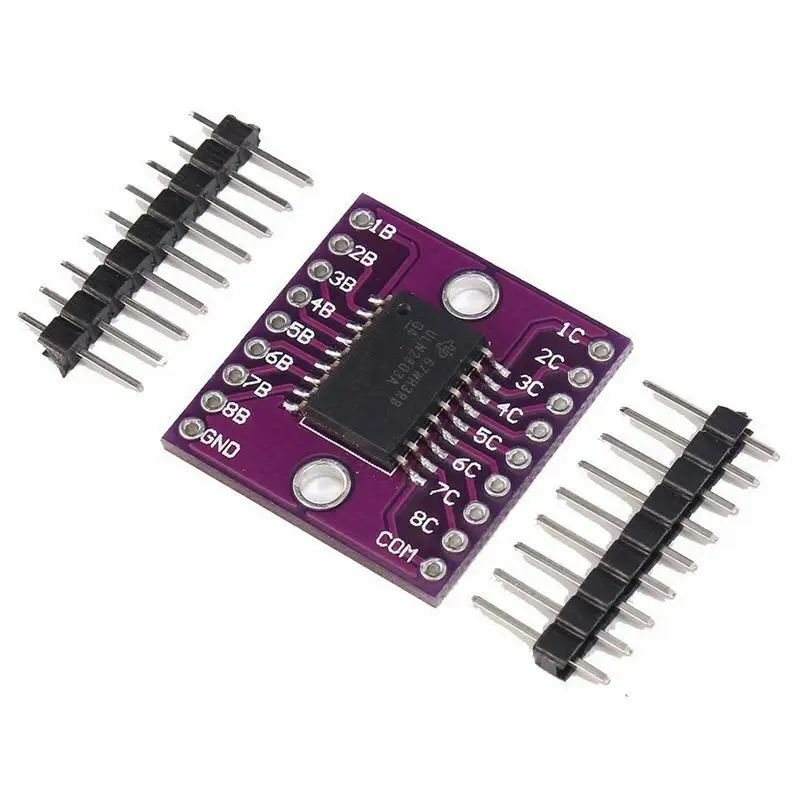
With these 5 V pumps, would I also need some ULN2003 stepper motor driver boards such as this?

https://www.ebay.com/itm/355059207786

With regards to the accuracy of the soil moisture sensors, I'm not sure that I will need very much accuracy for my project. My plan is to go ahead with capacitive moisture sensors, see if it works to keep the soil in the ideal moisture zone, and if not, take it from there.

The PSOC 5LP, at first glance, seems to be more complicated than working with Arduino - am I correct on this?
 
First and foremost the Arduino debug capability is primitive, and thats being generous.

The 5LP board has two 5LP chips on it, one for program/debug, the other the target.
Setting of watch points in memory, breakpoints, break and set values, examine HW,
all present in 5LP.
.
This took me ~ 10 min, its drag and drop, wire up to pins (simple mouse click process).

1696173397494.png


Drop the USBUART and LCD if you dont need them for user interface. I had them in
there so you could present a small QVGA display of the like to show moisture levels
by plant, eg, graph......

So use a scanning comparator (which it has) instead of SAR, if you only care about a
specific 1 level setpoint for all plants, then using the API f() calls in data sheet, no DMA,
everytime you get a trip ISR update the control reg bits to either turn on or off pump.
I used SAR because I thought flex for different plants, rates, might be of interest. So I
think total code needed ~ 25 lines of code as each component APIs simple to use,
you are not spending a lot of time trying to figure out specific bits of how to use a
piece of HW.

If you did the above now looks like :

1696173454954.png


Drop the output transistors and replace with ULN200x.....

Still on chip, the other 95% of chip resource available to do other stuff. This
you could put into PSOC 4, but I say 5LP because board costs lower and has
10X more HW in it to fool around with.

This is oversimplified but basically shows how fast stuff gets done in designing
in PSOC Creator, the IDE. Note he used the full up board, you do not need that,
the $15 board more than capable.


Regards, Dana.
 
Note I can easily add a ramp generator (again all on chip) to use to test the inputs :

1696178799204.png


One could even add internal mux / demux to scan and test all inputs at user request.

The capabilities of this SOC (System on Chip) simply great to work with.

Lastly one other thought, For scanning comparator approach, would be easy to use
one of the 4 onchip DACs to set trip points/channel, to handle varying plant water
requirements. PSOC simply has terrific flexibility.
 
Last edited:
How much water do you need to pump? The startup current for the first and third pump may be too great for the ULN2003 to handle. The second pump lists a current of 200mA, so the 500mA limit of the '2003 gives you some headroom. The 2nd pump is rated for 148mL per minute.

If that flow rate isn't great enough, you have a couple options:

● Use N-channel MOSFETs instead of the ULN2003s.

● Use higher voltage pumps (which should use less current for higher flow rates.

Both the ULN2003 and N-channel MOSFETs switch the LOW side of the load to GROUND. The 5V output of an Arduino can control either type device to switch loads of higher voltage (50 volts or more). The complication of this approach is powering the Ardunio. A linear regulator dropping 12 volts to 5 volts dissipates a lot of heat. Switching 7805 regulator replacements are available pretty cheaply, as are switching buck converter modules.

One gotcha of the '2003 stepper motor modules is that only 4 output channels are wired out.
 
Does any of these seem preferable? Otherwise I can just buy one of each and see which one is best, if any.
I'd go with one of the black ones - they look to be the same item from different sellers? Those appear better made and more likely to be serviceable, such as replacing the pump tube. The white one looks to be glued together.

If you are not bothered about LEDs, you could use octal darlington modules, they are cheaper. You could parallel two channels for each motor, so still four per module.

(Also on amazon & ebay etc).

A 1A supply may be OK for the motors, though the starting current is likely a lot higher than the running current, for a fraction of a second.

I'd be wary of running the MCU on the same supply, unless you feed it via a diode and large capacitor to prevent the voltage being pulled down as a motor starts up.
 
rjenkinsgb , do you think the ULN2003 (rated for 500mA) provides enough margin for the pump which is rated at 450mA? I'm a bit concerned about starting current exceeding the '2003 spec. Considering the pump isn't pumping against pressure, it might be ok.
 
That's why I suggested the eight channel board, with two parallel channels for each relay - it gives much better protection against start up surges.

With only a 1A power supply, there cannot be more than 1 or possibly two pumps running at a time, so the drivers should be OK with that.
 
Oh, missed the 2 channels in parallel! So sorry.
 

Latest threads

New Articles From Microcontroller Tips

Back
Top