Electro Tech is an online community (with over 170,000 members) who enjoy talking about and building electronic circuits, projects and gadgets. To participate you need to register. Registration is free. Click here to register now.
Welcome to our site! Electro Tech is an online community (with over 170,000 members) who enjoy talking about and building electronic circuits, projects and gadgets. To participate you need to register. Registration is free. Click here to register now.
How am I able to check if a frequency is being generated by my quartz crystall without getting an expensive oscilloscope? Will a LED work? I doubt that my crystall generates a frequency at all :? I just can't get it to oscillate! Any help?
the frequency will probably be too high for it to be detectable on an LED.
Some multimeters have a frequency testing function...
alternatively, you could geed the signal into a (for example) 4017, so that the frequency is divided by 10, and there is more chance of you being able to see the LED flashing...
If you can tell us roughly what frequency you expect it to be oscillating at, we might be able to suggest something more appropriate.
Also, if you post the circuit you are using, we could tell you if it should be working...
Im using a 4,096Mhz crystal, I have tried using a 4040 (12-stage binary counter chip) to divide the frequency down to 60Hz, but still the LED won't indicate any frequency. The circuit I'm using is this :
Only difference is that I'm using a 7404 hex inverter chip instead of the hex Schittrigger inverter shown.
Many oscillators generate a lot of extra noise that can be heard on an AM radio that is placed extremely close to the oscillator. It's crude but it works. Won't tell you the frequency but if the oscillator is making noise it's oscillating.
A capacitor will conduct AC but not DC. If you have a DVM you might consider making a simple probe that's a small capacitor to conduct AC but not DC and a diode to rectify the AC (RF if you prefer). Any significant voltage ought to be the result of AC coupled thru the capacitor. If AC is there it's likely the result of the oscillator. Do a google search on RF probe and you'll find good examples - real simple stuff but effective tools.
A simple shortwave receiver might be used to determine the frequency of you place the antenna close to the oscillator. It's likely to be heard as a hiss unless it's a particularly noisy oscillator.
A dip-meter, whether old grid dip or solid state, often has a function that turns off the oscillator so you get the equivalent of a tuned field strength meter. Again, not for precision measurement but it might be effective.
I doubt the 7404 inverter would work in this circuit, standard TTL has fairly low input impedance. Use a CMOS (CD4000 or 74HC) inverter as shown, they have much higher input impedance.
Im using a 4,096Mhz crystal, I have tried using a 4040 (12-stage binary counter chip) to divide the frequency down to 60Hz
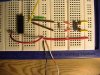
I have tried the trick with a radio, but with no luck though. :? Here is a picture of the actual circuit setup on a breadboard. Using a 7.680Mhz crystal instead of the 4.096Mhz.
You might get that to work if you change the inverter to 74HC04 as suggested, and add a 100nF (0.1uF) capacitor between VCC and GND, with leads as short as possible. You could try it across your power rails (in the center of the picture), but right across the IC , pins 7-14, would be better.
Those breadboards have notoriously high stray capacitance. If you could shorten the wires, you would have a better chance. Stand the resistor on end, squeeze the leads of the crystal close together (you may have to extend them by soldering on some short bare wires), and move the caps so that all the parts go into the pin 12-13 buses (except the other ends of the caps, which you can stretch and bridge over to your GND rail).
A better option is to build the oscillator on a little piece of perf board that has a GND plane (or at least a good GND bus), and make it really tight, with the power supply decpupling cap added as mentioned. You only need 3 wires from the perf board to your breadboard.
What's really the difference betweent the LS and the HC range? The LS range is low power while the HC is... ? Bah, I begin to doubt that quartz crystals work at all. :wink:
The big problem is input current. The one meg feedback resistor won't come close to biasing the inverter in its active range. If you make the resistor small enough to satisy the bias requirements, the resistor will kill the "Q" on the crystal, and it won't oscillate, or at least won't be very stable. There are schemes that use TTL gates to make crystal oscillators:
YES! I got it to work! It's alive! ALIVE! *dancinghappydance*
Thanks all. I used **broken link removed** changing the 1.2k resistors with 1k ones, and using a 74LS04 chip despite the 74F04 that have been used there. The cap used was torn from an old powersupply in a desperate effort to make the crystal oscillate when the 22pF and 39pF failed to do so. I also kept the wires as short as possible, and now it works!
This site uses cookies to help personalise content, tailor your experience and to keep you logged in if you register.
By continuing to use this site, you are consenting to our use of cookies.