hi! i need to know what is DC offset and why are we trying to reduce it
in audio output?
has to do anything with the centering of the waveform?
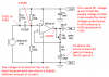
http://imageshack.gr/viewer.php?id=624938diagram3.jpg
thank you!")
in audio output?
has to do anything with the centering of the waveform?
http://imageshack.gr/viewer.php?id=624938diagram3.jpg
thank you!