Continue to Site

Welcome to our site!

Electro Tech is an online community (with over 170,000 members) who enjoy talking about and building electronic circuits, projects and gadgets. To participate you need to register. Registration is free. Click here to register now.

  • Welcome to our site! Electro Tech is an online community (with over 170,000 members) who enjoy talking about and building electronic circuits, projects and gadgets. To participate you need to register. Registration is free. Click here to register now.

HOW CAN I MAINTAIN HIGH CURRENT IN NEGATIVE DC TO DC REGULATOR?

Status
Not open for further replies.

Philenius

New Member
I have a project to design a negative DC regulator.
I have a batter of 48Vdc with 50ah so I want to regulate the voltage from -48vdc to -12vdc without affecting the current of 50ah. Please I need help anyone help me a diagram of that circuit or which is relating to my project or a advice. Remember am stepping down negative voltage.
 
You need to be far more specific, for a start how much is the maximum current that will be drawn (50aH isn't a current value, it's storage capacity), what exactly is it doing, and why do you think you need a negative regulator?.
 
I have been asked to design such a regulator. (Is there some reason why the battery and the load are both negative?) I do not understand this question, what are you meaning.
 
If you have a 50 AH battery and you wish to supply 50A to a load, what happens when the battery is discharged to a lower voltage value? What happens when it can no longer supply any current to the load because it has become completely discharged?
 
Most power dc supplies are positive, and the negative of the power supply is considered 0 V or earth. For example, vehicles have the negative of the battery connected to earth, and the +ve is 12 V (or 24 V for lorries).

Where there are mixed supply voltages, such as a laptop supplied at 18 V, with 5 V USB connections, both the 18 V and the 5 V are referenced to the same point, the chassis of the laptop.

As a result if is far more common to find circuits and voltage converters that use positive voltages. A 24 V to 12 V converter will almost always have the -ve and of the input connected to the -ve of the output.

There are systems that have negative supplies. Telephone systems are usually -48 V. Older cars (pre 1960) were often positive earth, so the chassis was connected to the +ve of the battery.

Where you have said that the battery voltage is -48 V and -12 V is needed for the generator, that implies that the +ve of the battery is connected to the +ve of the generator, and that doesn't seem to be likely. It would be good to know more about the generator to know what the power is being used for.
 
Seems like there is some confusion here.

Why would you supply 50 amps TO a "tower generator"? Charging a battery from a (wind turbine?) generator would be the usual case.

And if the battery/buck converter is isolated from the rest of the system, would regulating to +12v and connecting the generator with the correct polarity accomplish the same thing?
 
A buck regulator to convert -48 V to -12 V at 50 A is possible, but it would not be an easy project to start on.

A buck regulator works by initially connecting an inductor between the input voltage and the output voltage. The current in the inductor builds up, storing energy in the inductor. When the current gets too large, the power is cut off, so no current is taken from the supply and the current comes from the inductor. The current reduces in the inductor, and the inductor transfers its energy to the output.

For small buck converters, there is a Schottky diode to allow the current in the inductor to flow to the output when the power is turned off. For larger supplies, the power loss in the Schottky diode would be too much so there is an additional transistor, usually a MOSFET, to short out the Schottky diode when the power is off. For a 50 A converter, you would need that. The technique is called "Active rectification" if you want to look that up.

A buck converter is usually quite efficient, so to produce 50 A on average at -12 V would only need an average of around 15 A at -48 V. The current will be taken in pulses, so when current is being taken, 50A or more will flow from the battery, and nothing when the power is coming from the inductor. That will result in problems and you will need large capacitors on the input and output of the buck converter.

For 50 A output, it would be better to have several buck converters arranged so that the current flow is more even. With 4 converters, producing 50 A in total, at any one time you would have one converter consuming 12.5 A from the supply while energy is building up in its inductor, while the other three would each be producing 12.5 A as energy is taken from the other inductors.

That is called a "Multiphase buck regulator" and it is explained here:-
https://www.ti.com/content/dam/vide...p4/subassets/4.2-multi-phase-presentation.pdf
That technique is used in computers where the processor runs on very low voltages but takes high currents.
 
I have a project to design a negative DC regulator.
I have a batter of 48Vdc with 50ah so I want to regulate the voltage from -48vdc to -12vdc without affecting the current of 50ah. Please I need help anyone help me a diagram of that circuit or which is relating to my project or a advice. Remember am stepping down negative voltage.
OK I think we have the AH rating resolved. A12 volt 50 AH battery will deliver 50 amps of current at 12 volta for an hour or 100 amps at 12 volts for a half hour or 25 amps of current for two hours and so forth. All here nor there other poor terminology leaving myself and others wondering exactly what you want?

Next what is a tower generator? I assume a generator atop a tower such as a wind turbine generator? If yes, then call it what it is. Try to explain your project exactly in detail using correct terminology.

Seems like there is some confusion here.
To say the very least. :)

Ron
 
Next what is a tower generator?

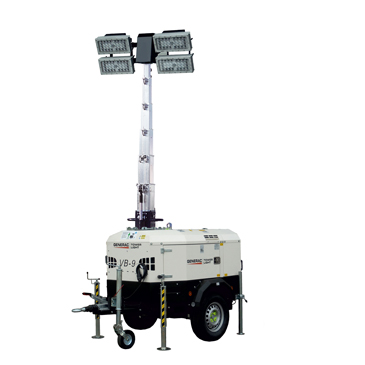
I was guessing this type of thing - but likely wrong, with the minimal info!!

8874040262686.jpg


-12Vdc to -14Vdc with a current of 50A. according to my generator

The 50AH battery capacity or requirement has no correlation to the current needed for whatever 12V device or system you are trying to run.

It could be anything from 12V at a trivial current, to 12V at 300 - 700A or more, such as a normal 12V vehicle starter battery can deliver!

Please provide full information on exactly what devices or machines you are trying to connect and for what exact purpose.

Too many details don't hurt, leaving anything out just wastes everyone's time and puts people off from responding further.
 
I'm wondering if the tower generator has a diesel engine to run the generator, but also a big battery to keep some or all of the lights going for some time without the engine running. There would also be a 12 V battery to start the diesel engine.

Is the idea to dispense with the 12 V battery and start the diesel engine from the 48 V battery?

If so, the 48 V battery is very unlikely to have it's positive connected to the positive of the 12 V battery.

Making a converter that will run a 12 V starter motor will be really difficult. I would rewind the starter motor with more turns of at thinner wire, or find a 48 V starter like the ones on some mild hybrid cars.
 
Last edited:
Yap exactly

Exactly WHAT generator make and model, or engine make and model is it?

The ONLY way you will operate a a typical diesel engine 12V starter motor, without a device costing thousands, is with a 12V vehicle starter battery!

Using a 48V to provide a moderate charge to that battery to keep it topped it and ready is a very different matter and would be cheap in comparison.
 
Status
Not open for further replies.

Latest threads

New Articles From Microcontroller Tips

Back
Top