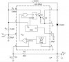
Yes the MC34063 is an old IC, as most people say, but this is the only dc dc converter that seems to impress me since I learn a lot from it, so I don't want to throw it out for now. I have one issue on the output voltage/current. The schematic is attached.
I am stepping up (boost) voltage from 9v to 11v at 7mA current. The problem is, when I put load on the output, the voltage drops 4 volts (becomes around 7.4v) bellow the main voltage output which is 11v at 7mA. I am still confused as what the reason is for this. Is it the axial inductor that I am using which is causing this huge voltage drop on the output? The Vf is a shottky diode 1n5819 ,which seems fine to me, unless I switch over to a 1n5817 becuase of the lower voltage drop??
The switching frequency is at 100Khz
Duty Cycle at 25%
Voltage ripple is at 0.1V
Iin at max is 0.019A
Iout is 0.007mA
Another question. Is it best to lower 9v battery to a smaller voltage battery to get an 11v output? I need to be sure that I use up the entire battery until it is literally dead, but used for a long time. As usual, lowering current is important in general for battery applications. That is why I chose 7mA as the output current.
Attachments
Last edited:
")
