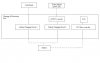
1. You show a bipolar in the pic. A MOSFET is a much better idea for the high efficiency you require. Look for one listed as "logic level".
Sorry, the Figure has not been updated. Real sorry. I'm now trying to use the BSH102 MOSFET, but I couldnt find this part here. Looking for a replacement, any suggestions?
2. The Zener is unnecessary. It is not a good mechanism to prevent overcharging, and in any case these currents are far too low to damage the battery through overcharging. Frankly, it will be a miracle if you manage to charge the battery in the first place.
Thanks for that advice, I will now remove the zener diode. But would you mind to suggest a method for me to prevent overcharging? The small current output from my panel might not overcharge the battery but I would like to get some info about methods to prevent overcharging. Mind to give some advice?
3. The capacitor is probably unnecessary. The battery will charge about the same if it's 30 mA pulsed at 50% or 15mA filtered into a constant DC current. I doubt it will do anything helpful, and if it's got a poor leakage resistance, will drain a small amount of current (under 1mA, but it's there) all the time.

Blur here. I thought the purpose of the capacitor is to perform some boost function during the charge-discharge process? :? Sorry, this seem to be a real nonsense from me. Mind to explain further?
The inductor size is important. If it's too low, the solar cell will be loaded with ripple current. This is not damaging, but the efficiency suffers since the solar cell is only optimally loaded at one voltage/current point and a ripple by definition means the current will vary over the period of the PWM.
Thanks a lot. I've tried simulating using 100mH and it seems that it works well, I don't get much ripple. But I will try again I practical.
")