williB
New Member
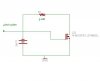
the microchip site has a transformerless powersupply design ,but it is anly good for a few mA..that the PICs use..devonsc said:Hi there, I've read about the implementation of transformerless AC/DC converter. Not implementing this in the project, just want to ask something this form of AC/DC converter.
...
did u order your PIC ?
 Mind correcting me? :cry: