Continue to Site

Welcome to our site!

Electro Tech is an online community (with over 170,000 members) who enjoy talking about and building electronic circuits, projects and gadgets. To participate you need to register. Registration is free. Click here to register now.

  • Welcome to our site! Electro Tech is an online community (with over 170,000 members) who enjoy talking about and building electronic circuits, projects and gadgets. To participate you need to register. Registration is free. Click here to register now.

Crystal Tip

Status
Not open for further replies.

AtomSoft

Well-Known Member
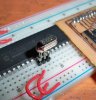
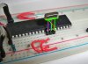
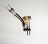
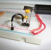
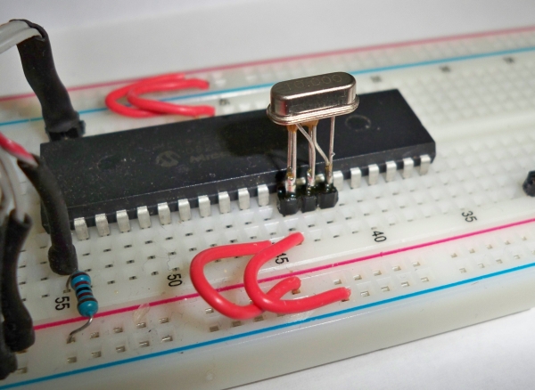
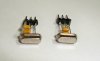
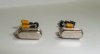
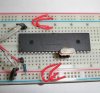
hey guys i know messing with crystals on a breadboard can be a small hassle. i just realized i never showed anyone how i deal with it and decided to share my tip.. if you can solder then you can do this... below are pictures of a 10mhz and 20mhz crystal and 2 caps tied to 3 pin header. so you can simply plug and play. i have not ran into any issues using this yet so... anyway here are the pictures and feel free to recreate and use these as much as you want:

2-jpg.35565


3-jpg.35566


4-jpg.35567


5-jpg.35568
 

Attachments

  • 1.jpg
    1.jpg
    119.5 KB · Views: 127
  • 2.jpg
    2.jpg
    105.2 KB · Views: 371
  • 3.jpg
    3.jpg
    138.7 KB · Views: 402
  • 4.jpg
    4.jpg
    170.3 KB · Views: 381
  • 5.jpg
    5.jpg
    245.3 KB · Views: 398
Very clever! It's the simplest things that show real brilliance. :)

Maybe a possible improvement would be to put a black sharpie spot on the side of the xtal that is the ground pin?
 
The middle pin is the ground pin. The outer two pins go to the crystal leads.

Neat idea though. It makes you wonder why crystals don't come with the caps built in. Probably because different applications need different cap values?
 
Last edited:
nope the left end pin is ground. This is so you can plug and play to a breadboard.... ill take a pic:

6-jpg.35569


7-jpg.35570
 

Attachments

  • 6.jpg
    6.jpg
    254.3 KB · Views: 361
  • 7.jpg
    7.jpg
    184.7 KB · Views: 365
Last edited:
Soldering the caps to the crystals like that makes it a nice module but I don't get the reason for it being an inch tall.
 
Last edited:
That's brilliant but that wont work on my 18 pin uC as the positive pin is next to the crystal instead of the ground :(
 
im thinking of making pcb modules with right angle pins.... ill talk to a friend and see if he would like to make some PCBs and sell them with pin header only. this way users can install there own caps and crystals to customize the application.
 
Last edited:
Some ceramic resonators come with capacitors built in.

You can connect the capacitors to +ve instead of negative, as long as your suppressors are large enough.

Alternatively, just use an oscillator. Much easier.
 
Nice idea on the crystal.

I build processor modules using SOIC's and TQFP chips. For me the best layout is to span the power strip between two breadboards. That gives you about an inch for the board and a full row of exposed BB socket holes on each side.

The modules have an ICSP connector, bypass caps, and an LED to indicate power. I often keep the pinout in the original order execpt for VSS and VDD which I move to end (both rows). The power location allows me to insert LCD and other boards next to the power module without wiring.

For these modules I use chips with internal clocks but one can always use an external. If anyone is interested I can post images when I find my camera :)

------------

Unless I have a need for the better accuracy I use 3 pin oscillators with internal caps.

3v0
 
Last edited:
Status
Not open for further replies.

Latest threads

New Articles From Microcontroller Tips

Back
Top